
Output input can be balanced equilibrium Repeater

The described circuit is a dual differential amplifier configuration that offers balanced input and output characteristics, making it suitable for various applications including audio processing and signal conditioning. The differential inputs, +IN and -IN, are designed to receive signals that are equal in magnitude but opposite in phase, which enhances noise rejection and improves signal integrity.
In this configuration, the use of eight identical resistors is critical. This uniformity ensures that the gain and bandwidth of the amplifiers remain consistent and predictable. The choice of resistor values is crucial; lower resistance values are preferable for high-frequency applications to reduce noise and improve bandwidth. Conversely, higher resistance values are suitable for low-frequency applications where noise is less of a concern.
The circuit's output is phase-coherent, meaning that the output signal maintains the same phase relationship with respect to the input signals, albeit inverted. This property is particularly useful in differential signaling applications, where maintaining signal integrity is paramount.
To optimize performance across different frequency ranges, adjustments to the resistor values may be necessary. For applications involving video frequencies, it is advisable to reduce the resistance to minimize the impedance seen by the circuit, thereby enhancing the response time and overall performance of the amplifier.
In summary, this differential amplifier configuration is designed for versatility and efficiency in handling a range of frequencies, with careful attention to resistor selection and configuration to achieve optimal performance in various electronic applications. As shown, the upper and lower symmetric configuration two basic differential amplifier, differential input + IN and -IN are respectively connected cares balanced input. Because the output signal components bowed fJ is inverted, so reverse the input side, the output phase-coherent.. Although the total required eight resistors, but all the same resistor, the resistance in order to best use complex sets of eight resistors of at low frequencies.
Resistance values take lOk ~ lOOkQ more appropriate. j video frequencies, as it must be reduced. Circuit impedance.. This resistance is desirable elbow IK ~ SK moth butterfly while mountain in bad characteristic rrLua2 J shall be elected for tax enlarged scale clamor use of the band.
Related Circuits
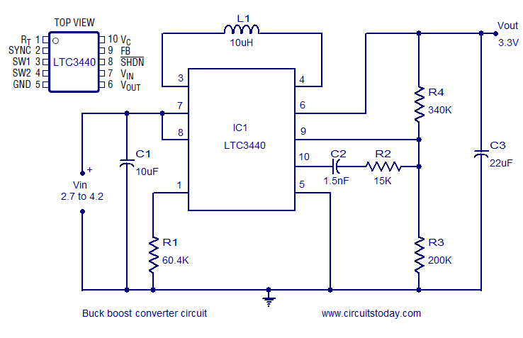
A simple and highly efficient buck-boost converter is implemented using the LTC3440 integrated circuit. The output voltage is set at 3.3V, while the input voltage range can vary from 2.7V to 4.2V. The LTC3440 is a synchronous buck-boost converter designed...
This circuit determines whether multiple inputs in a digital input group are active. It provides a digital measurement of the number of active inputs and allows for the establishment of a threshold for majority-decision applications. This means it can...
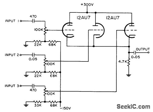
Each grid is biased to cutoff, allowing the mixer to accept only positive-polarity pulses with sufficient amplitude to overcome this bias. -NBS, "Handbook Preferred Circuits Navy Aeronautical Electronic Equipment," Vol. 1, Electron Tube Circuits, 1963, p N4-2. In a typical...
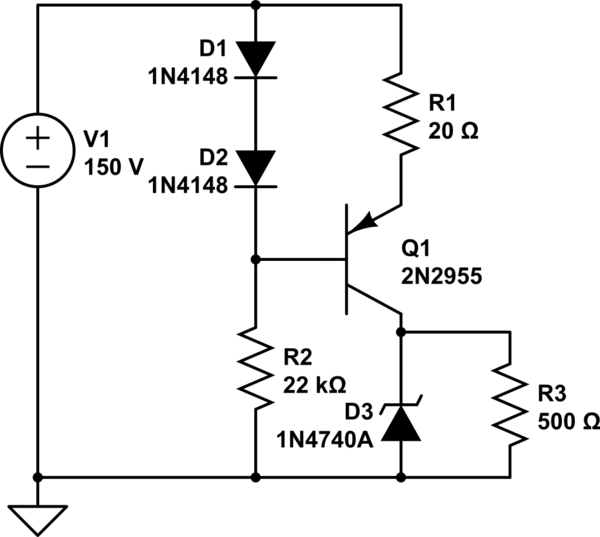
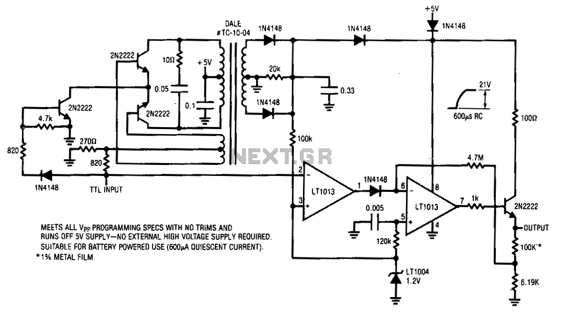
A simple low voltage/current power supply that can accept a wide range of input voltages, up to several hundred volts. The input range is specified as 20 to 160V DC, with an output requirement of 10V and a maximum...
There is an opportunity to utilize a condenser microphone amplifier in conjunction with a Very Low Frequency (VLF) receiver. Initial tests with a monopole antenna yielded positive results. The location is a small town designated as J041VG, with a...
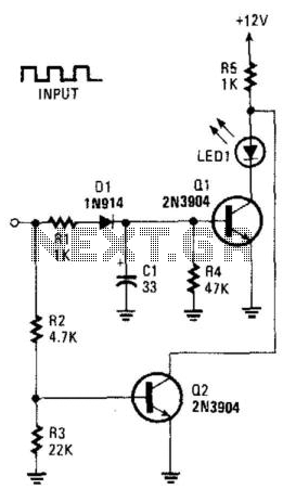
This circuit can be utilized to detect a stuck output or node in a circuit, or a loss of data or pulses. The pulse train charges capacitor C1 and biases transistor Q1 on, which illuminates the LED. If the...