Stalled-Output Detector

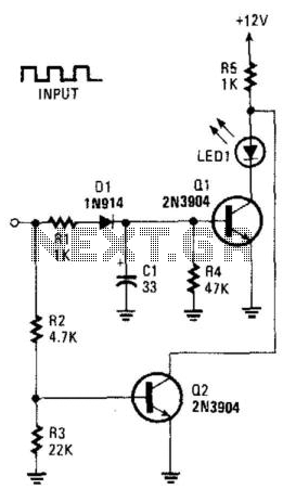
This circuit can be utilized to detect a stuck output or node in a circuit, or a loss of data or pulses. The pulse train charges capacitor C1 and biases transistor Q1 on, which illuminates the LED. If the input remains high, transistor Q2 turns off the LED.
This circuit functions as a detection mechanism for output states and data integrity in electronic systems. The primary components include a capacitor (C1), two transistors (Q1 and Q2), and an LED indicator.
When a pulse train is applied to the circuit, capacitor C1 begins to charge. This charging process causes transistor Q1 to enter a conducting state, allowing current to flow through the LED, which indicates that the circuit is operational. The illumination of the LED serves as a visual confirmation of a valid signal presence.
If the input signal remains in a high state for an extended period, transistor Q2 becomes activated. The role of Q2 is to monitor the input level, and when it detects that the input does not transition as expected, it turns off the LED. This action signifies that the output may be stuck or that there is a potential loss of data or pulse signals.
The design of this circuit is essential for applications requiring reliable data transmission and output monitoring. It can be particularly useful in digital communication systems, where signal integrity is critical. By incorporating this detection circuit, engineers can ensure that any anomalies in signal behavior are promptly indicated, allowing for timely troubleshooting and maintenance.
Overall, the circuit serves as a crucial tool in maintaining the functionality and reliability of electronic systems, providing both visual feedback and diagnostic capabilities. This circuit can be used to detect a stuck output or node in a circuit, or a loss of data or pulses. The pulse trai n charges CI and biases Ql on, which lights the LED. If the input remains high, Q2 extinguishes the LED.


