
An B3CKS beer can VLF Antenna

The surrounding mountains and buildings exceed the height of the QTH, leading to significant interference with VLF reception, including power line hum, broadband RF noise, and potential interference from modem or cable television signals. Reception includes numerous signals from the VLF band up to 108 MHz, which complicates VLF listening. Various antenna types have been tested, with limited success. Magnetic antennas (ferrite and loop types) successfully received sferics but introduced excessive hum and RF interference. Efforts to mitigate this interference have compromised the quality of sferics received.
Different electric antennas have been employed, achieving some success in listening to the VLF band with reduced hum and interference, although space limitations restrict the installation of larger antennas. The reception of sferics is obstructed by surrounding buildings, while broadband signals create a significant background noise. Most interference occurs within the frequency ranges of 3.5 kHz to 6.5 kHz and 8 kHz to 11 kHz. Consequently, outdoor locations are necessary for optimal reception.
Initial tests of the antenna produced favorable results until sunset, when numerous radio stations from various countries were received, with signals fading in and out. Following this, modifications were suggested, specifically changing capacitors C4 and C7 to 1.5 nF to block RF signals and adding a 15 nF capacitor in series with resistor R10. Additionally, to match the impedance from the input to the beer cans, resistors R4 and R9 were replaced with a single 10 MΩ resistor. Bridge 1 between ST3 and ST4 is not utilized; if closed, it would allow the amplifier to support electret microphones. Bridge 2 is also unused.
The circuit operates on a single supply voltage ranging from 5 to 15 volts, with a 9-volt battery being used. The amplifier generates sufficient signal strength to drive the line input of a PC soundcard with minimal noise, allowing for the use of another channel, such as a magnetic antenna. The output of the amplifier is connected in series with a 690-ohm resistor to the 24V side of a small transformer. The 230V side connects through a 10K, 10-turn potentiometer in series with a 2.5K resistor, allowing for variable resistance from 2.5K to 12.5K, facilitating the optimization of input levels to the soundcard.
To switch from floating mode to grounded mode, a switch is installed between the negative terminal of the battery and the ground wire connected to the soundcard. The antenna is housed within a 76 mm downspout, measuring 55 cm in length, with beer cans affixed using hot glue inside the downspout. The top is sealed with a cap and filled with silicone. The antenna wire extends through the lower end of the downspout to the amplifier, allowing for a 10 cm pull-out for repairs or modifications before final installation.
A connector plate is positioned 4 cm inside the pipe, providing protection against rain. This plate houses the power switch, the switch for changing between grounded and floating modes, the BNC output, and the 10-turn potentiometer. A hole is drilled in the bottom of the beer can to allow the cable to pass through, which is then sealed with glue. The ground wire is connected at the terminal and secured with adhesive.So there is a chance to use them in combination with a condenser microphone amplifier for a VLF Receiver. Bingo. The first tests as a Monopole gave good results. I live in a small town located at J041VG with approximately 7500 inhabitants. The height above sea level is between 220-650 m over NN. My QTH is in the middle of town and 330 m over NN. All the mountains and the buildings are higher than my QTH. To top it all I have many signals interfering with VLF reception such as power line hum, broad-band RF and possibly modem or cable TV interference. I hear many signals from the VLF band up to 108MHz. Certainly not good for VLF listening. I`ve tried numerous types of Antennas but so far not much satisfaction. The Magnetic type antennas (ferrite and loop) give good reception of sferics, but, unfortunately too much hum and RF.
All attempts to blank out this interference reduce the sound quality of the sferics. So I tried different electric antennas. With some of them I was able to listen to the VLF band without too much hum and interference at my QTH. Unfortunately I do not have the room to put up large antennas. The receiving of sferics is shielded by building around me and the broadband signals produce an incredibly loud background noise.
The bulk of the interference is between 3. 5KHz to 6. 5KHz and 8KHz to 11KHz. No other options. I must go out to open country. The first test of the antenna gave a very good result. . until sundown! Suddenly I heard many Radio Stations from different Countries and the signals faded in and out in varying cycles. So I was frustrated by this and went to bed. But someone :-) told me: "You have to change the capacitors in the circuit. " The circuit is modified by changing C4 & C7 to 1. 5nF to block the RF signals and adding 15nF to R10 in series. Also to compensate the impedance from the input to the beer cans R4 and R9 are replaced with a 10M resistor.
The bridge 1 between ST3 & ST4 is not used. If the bridge 1 is closed the amplifier will support a current for electret microphones. Bridge 2 is also not used. The circuit can be powered by a single supply between 5 and 15 volts. I use a 9 volt battery. The amplifier provides enough signal to drive the line input to the PC soundcard and produce relatively little noise. So you can use the other channel for instance with a magnetic antenna. The output of the amplifier is connected in series with a 690 ohm resistor to the 24V side of little transformer.
The 230V side is connected across a 10K, 10 turn, potentiometer. In series with a 2. 5K resistor so he resistance is variable from 2. 5K up to 12. 5K. So you can search for the best level for the input to the soundcard. he value of the resistance depends on the transformer. To change from floating mode to grounded mode add a switch between he minus of the battery and the ground wire to the soundcard. The antenna is mounted in a 76mm downspout. The length amounts to 55cm. The beer cans are glued with hot-glue in the downspout. The top is covered with a cap and is filled with silicon. The wire runs through the lower an down to the amplifier and it is possible to pull out of the downspout for 10cm.
This made it easy to repair the amplifier or to make changes before the final mounting. The connector plate is mounted 4cm inside the pipe to protect against rain. The right picture shows the connector plate. On the plate are mounted the power switch, the switch to change between grounded and floating mode, the BNC output and the 10 turn potentiometer. Drill a hole in the bottom of the beer can; push the cable through the beer can and glue it in place.
Connect the ground wire at the lustre terminal and fix it with glue. 🔗 External reference
Related Circuits
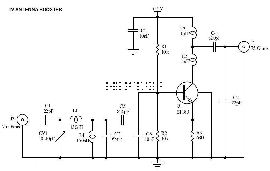
This is the circuit diagram of a UHF band TV antenna booster with a 15dB gain power. This low-cost antenna booster is simple and easy to build. This circuit is based on the BF180 UHF transistor. The first stage...
At VHF, both the 1/4-wavelength monopole and the 5/8-wavelength monopole antennas are widely used. The VHF 5/8-wavelength (144 MHz) vertical monopole has long held the reputation of providing about a 3-dB gain advantage over the 1/4-wavelength vertical monopole. The...
This UHF wideband amplifier (Ultra High Frequency amplifier) provides a total gain of 10 to 15 dB in the frequency range of 400 to 850 MHz, making it suitable for areas with weak TV signals. For optimal performance, the...
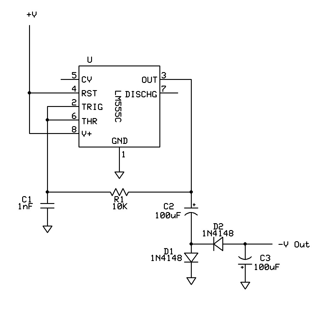
Can a 555 negative supply circuit, like the one below I pulled from another schematic, supply enough negative voltage to an LM324 and an AD736JN? The 555 timer integrated circuit can be configured to generate a negative voltage supply,...
Described here is a simple omnidirectional, vertically-polarised dipole for two metres. Made from coaxial cable, it can be rolled up and stored in a small container. It may be used as is indoors, or waterproofed for use outside. No...
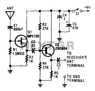
This circuit is designed to enable a short pull-up antenna to function similarly to a long wire antenna, without providing any voltage gain. The circuit enhances the receiver's performance only if the signal at the antenna is sufficiently strong...