
Over Voltage Protector

The Over Voltage Protector circuit typically employs a voltage sensing mechanism to monitor the input voltage level. When the voltage exceeds a predetermined threshold, the circuit activates protective measures to prevent damage to connected appliances.
Key components often included in this circuit are:
1. **Voltage Sensor**: This component detects the input voltage and triggers the protection mechanism when the voltage exceeds the safe limit.
2. **Zener Diode**: A Zener diode may be used to clamp the voltage to a safe level. It allows current to flow in the reverse direction when the voltage exceeds a specific value, thus protecting downstream components.
3. **Relay**: A relay can be utilized to disconnect the load from the power supply when an overvoltage condition is detected. This component provides electrical isolation between the control circuit and the high voltage circuit.
4. **Fuse**: A fuse serves as an additional layer of protection by breaking the circuit in case of excessive current flow, which can occur during overvoltage conditions.
5. **Capacitors and Resistors**: These components are used for filtering and stabilizing the voltage readings, ensuring accurate detection and response to overvoltage situations.
The circuit diagram typically illustrates the interconnections between these components, showing how the voltage sensor interfaces with the relay and other protective devices. The parts list will provide specifications for each component, such as voltage ratings, power ratings, and recommended types, to ensure compatibility and effectiveness in the circuit's operation.
This Over Voltage Protector circuit is applicable in various electronic projects, particularly where sensitive devices require protection from voltage spikes or fluctuations, enhancing overall reliability and longevity of the connected appliances.Over Voltage Protector is a simple circuit used to protect appliance from over voltage circuit diagram with parts list of over voltage protector various electronics project. 🔗 External reference
Related Circuits

Consider a capacitor with capacitance C that charges to a voltage V and discharges to 0V at a frequency of 5 times per second. To estimate the average current, also referred to as the RMS current, a rough approximation...
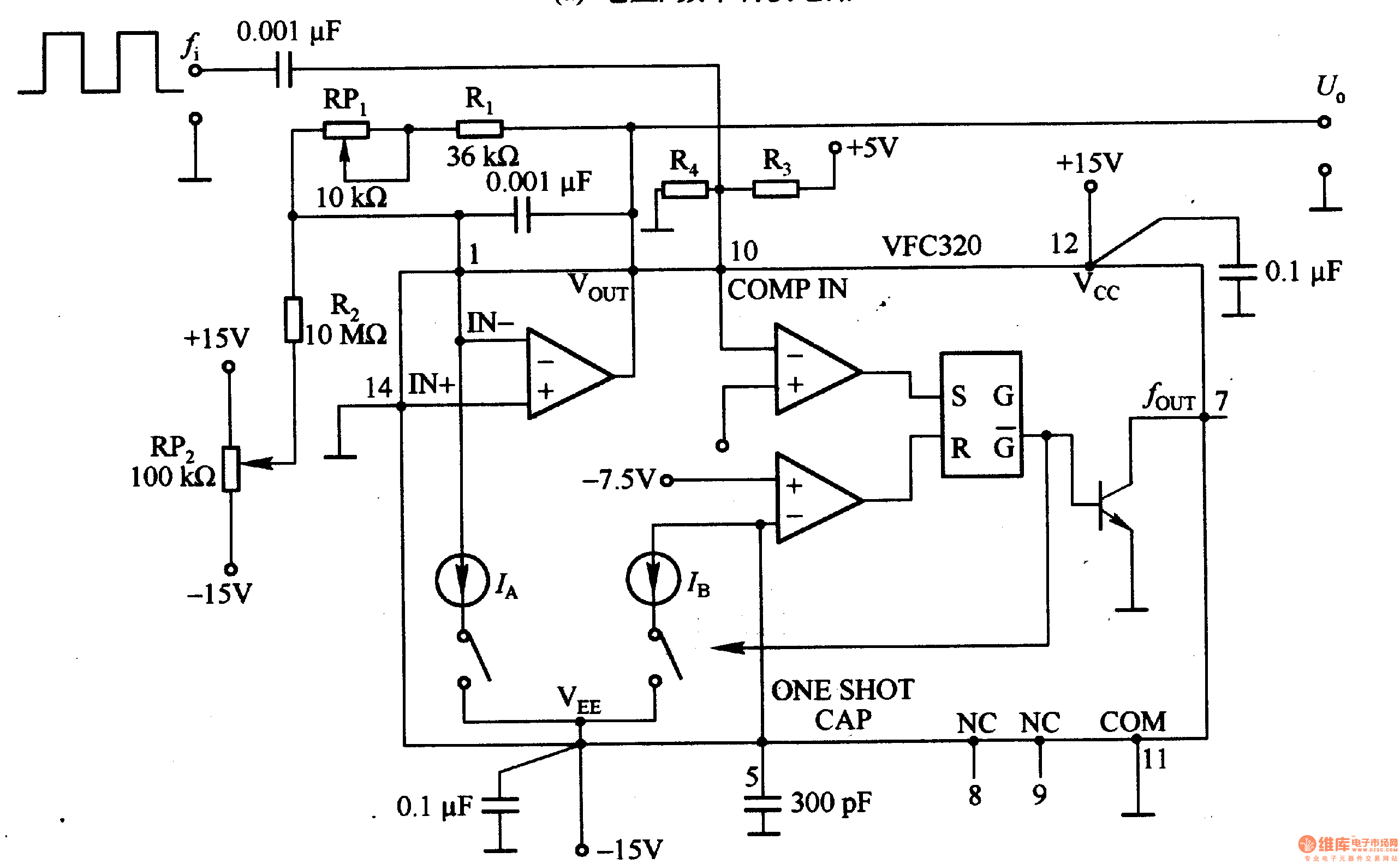
Figure 1-22 (a) illustrates a circuit that converts an input voltage of 0 to +10V (Ui) into a pulse with an output frequency ranging from 0 to 100kHz. In this configuration, pin 7 of the VFC320 is connected to...
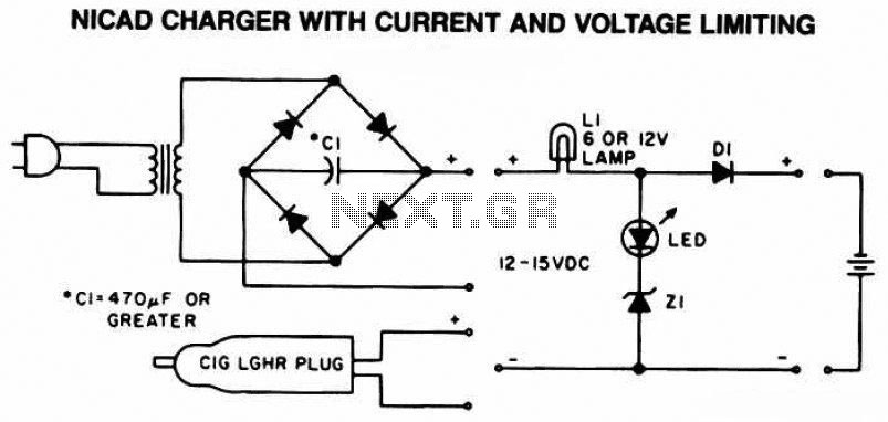
The following diagram is the schematic of a Ni-CAD battery charger circuit, which includes current and voltage limiting features to extend the battery's lifespan. The lamp L1 will illuminate brightly, and the LED will be off when the battery...
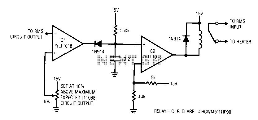
This circuit responds quickly enough to prevent damage from most overloads. Capacitor C1's input is connected to the output of the LT1088 servo circuit. If the LT1088 circuit's output exceeds the threshold at C1's other input, C1 trips, discharging...
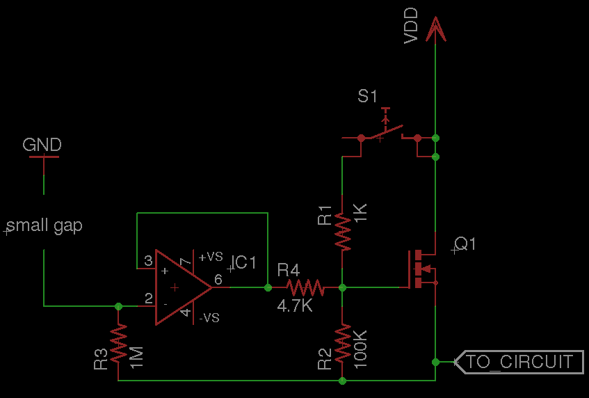
A circuit that requires protection from high voltage. Is there a component other than a fuse that does not need to be replaced every time? Something like a switch that activates only when high voltage is supplied, diverts the...
The simplest current-to-voltage (I to V) converter is a basic resistor. However, the disadvantage of this simple configuration is that it presents a nonzero impedance to the input current source. The I to V converter is an essential circuit in...