
50MW Audio Amplifier circuit

The described audio amplifier circuit is designed to deliver efficient sound amplification while maintaining a compact form factor. The input stage is crucial for preparing the audio signal for amplification, ensuring that the signal is properly biased to optimize performance. The use of complementary output transistors enhances the amplifier's efficiency and linearity, allowing for a more faithful reproduction of the input signal.
The 3-ohm resistor in series with the emitters plays a vital role in thermal stability. As the temperature of the transistors increases, their characteristics can change, potentially leading to thermal runaway. By stabilizing the bias current, this resistor helps to mitigate these effects, thereby improving the reliability and longevity of the amplifier.
The input impedance of 500 ohms indicates that the amplifier can interface well with a variety of audio sources without causing significant loading effects. The voltage gain of five to eight is suitable for driving typical small speakers, providing adequate amplification for casual listening environments.
The 2-volt swing across the 8-ohm speaker represents a significant output level, especially given the compact size of the amplifier. The ability to deliver 50 milliwatts of power makes it suitable for personal audio applications, such as small portable speakers or headphone amplifiers.
Incorporating heat sinks into the design of the output transistors is recommended to dissipate heat generated during operation, especially when the amplifier is driven hard. This addition not only enhances performance but also prevents overheating, which can lead to circuit failure.
Overall, this small audio amplifier circuit exemplifies a practical approach to audio amplification, balancing performance, efficiency, and thermal management within a compact design suitable for various electronic projects.Welcome to the weblog where we discuss about electronic circuits schematics, PCB design, diy kits and electronic projects diagrams. The following is a small audio amplifier comparable to what you may come across a small transistor radio medium size.
The input stage is biased to ensure that the power is divided equally to provide the two complimen tary output transistors which are slightly biased in conduction of the diodes between the bases. A 3. three ohm used in sequence for the use of the issuers of the output transistors to stabilize the bias current that does not change significantly with temperature or several transistors and diodes. Due to recent increases in bias voltage between the emitter and base decreases as a result of minimizing driving.
Input impedance is 500 ohms and the voltage gain is approximately five to eight ohm speaker connected. The voltage swing around the speaker is 2 volts without distorting production and capacity is at the same time in the 50 milliwatt range.
A high voltage provided as well as the addition of heat sinks in the output transistors would be a great source of more power. Circuit thirty milliamperes draw a supply of 9 volts. 🔗 External reference
Related Circuits
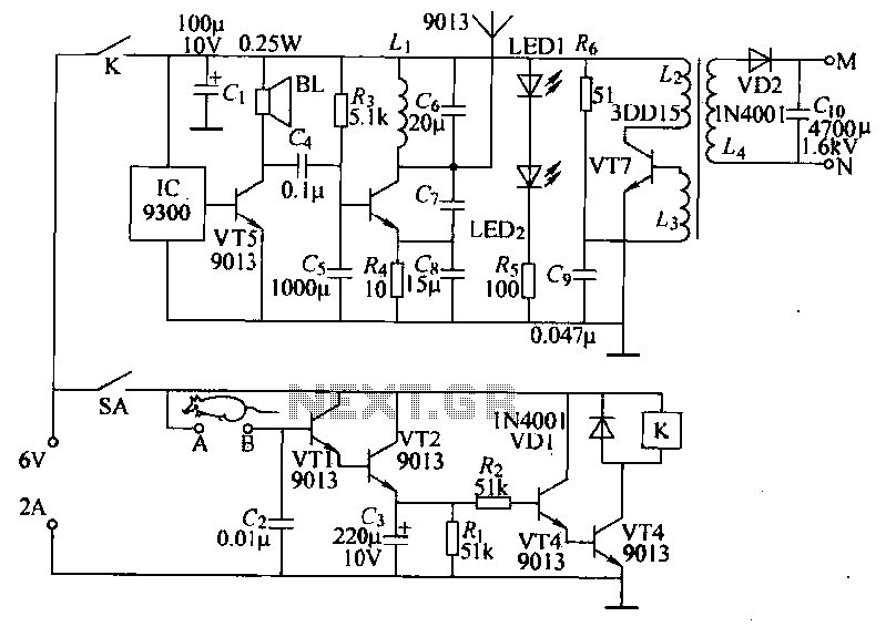
Power-saving electronic mousetrap. This example describes the minimal power consumption, which only occurs when a mouse enters the control zone during foraging activities. After a 30-second delay, the system enters a wait state, making it suitable for outdoor use....
This is a classic frequency divider by two, implemented using a T-flip flop circuit, specifically with IC1 [4011]. In this circuit, the frequency from the network, after limiting the negative half-period of the sine wave and transforming it into...
This DC drill speed controller circuit allows for the adjustment of the rotational speed of a drilling machine. A mini-drill machine is always... This circuit utilizes a pulse-width modulation (PWM) technique to control the speed of a DC motor, which...
This circuit is designed to demonstrate high frequency and high voltage, capable of producing up to approximately 30 kV, depending on the transformer utilized. It is an economical and straightforward project, primarily using a standard TV flyback transformer. The...
A Variable DC Power Supply is an essential tool for electronics hobbyists. This circuit is not entirely new, but it is simple, reliable, robust, and short-proof, offering variable voltage up to 24V and variable current limiting up to 2A....
This simple circuit is designed to provide an output power of approximately 1 watt when connected to a 9-volt power supply. The key advantage of this circuit is its use of a dual Darlington configuration, which increases the input...