
Parallel Port Interface with relay

There are three possible base addresses for the parallel port. You may need to try all three base addresses to determine the correct address for the port you are using but LPT1 is usually at Hex 0378. The QBasic "OUT" command can be used to send data to the port. OUT, &H0378,0 sets D0-D7 low and OUT, &H378,255 sets D0-D7 high. The parallel port also provides four control lines (C0,C1,C2,C3) that can be set high or low by writing data to the base address+2 so if the base address is Hex 0378 then the address of the control latch would be Hex 037A. Note that three of the control bits are inverted so writing a "0" to the control latch will set C0,C1,C3 high and C2 low.
To implement the described relay control circuit, the following components are required: a parallel port interface, a solid-state relay (SSR) or mechanical relays, transistors (for mechanical relays), resistors (300 ohm for SSR), and a power supply (5 volts).
In Figure A, the solid-state relay is connected to one of the data lines (D0-D7) of the parallel port. The 300-ohm resistor serves to limit the current flowing into the input of the SSR, protecting the parallel port from excessive current draw. When a logic "0" is sent to the data line, the SSR is activated, allowing current to flow through the load connected to its output.
Figures B and C illustrate the use of mechanical relays. In Figure B, a transistor is used to control the relay. When a logic "1" is sent to the data line, it turns on the transistor, which in turn energizes the relay coil, closing the relay contacts. Conversely, in Figure C, the transistor is activated by sending a logic "0" to the data line, thus energizing the relay in this configuration. This dual setup allows for flexible control of different load types depending on the logic state sent from the parallel port.
The common ground connection from the power supply to the parallel port's ground pins (18-25) is essential for ensuring that all components operate within the same reference voltage level, preventing potential floating ground issues that could lead to erratic behavior or damage to the components.
The parallel port's base address is critical for correct operation, with Hex 0378 being the most common for LPT1. The use of the QBasic "OUT" command allows for straightforward manipulation of the data lines and control lines. The control lines (C0-C3) can also be utilized to manage additional functions or to provide feedback from the relays, with the inverted logic of some control bits requiring careful programming to ensure correct operation.
This setup provides a versatile and effective means of controlling relays directly from a PC, suitable for various automation and control applications.Below are three examples of controlling a relay from the PC's parallel printer port (LPT1 or LPT2). Figure A shows a solid state relay controlled by one of the parallel port data lines (D0-D7) using a 300 ohm resistor and 5 volt power source. The solid state relay will energize when a "0" is written to the data line. Figure B and C show mechanical relays controlled by two transistors. The relay in figure B is energized when a "1" is written to the data line and the relay in figure C is energized by writing a "0" to the line.
In each of the three circuits, a common connection is made from the negative side of the power supply to one of the port ground pins (18-25). There are three possible base addresses for the parallel port You may need to try all three base addresses to determine the correct address for the port you are using but LPT1 is usually at Hex 0378. The QBasic "OUT" command can be used to send data to the port. OUT, &H0378,0 sets D0-D7 low and OUT, &H378,255 sets D0-D7 high. The parallel port also provides four control lines (C0,C1,C2,C3) that can be set high or low by writing data to the base address+2 so if the base address is Hex 0378 then the address of the control latch would be Hex 037A.
Note that three of the control bits are inverted so writing a "0" to the control latch will set C0,C1,C3 high and C2 low. 🔗 External reference
Related Circuits
You can make your own 2-meter "rubber duckies" that will likely perform much better than many commercial units. I compared my design with two other "rubber duckies" of the TH215 and ICT7 which outperformed them both. With the "duckie"...
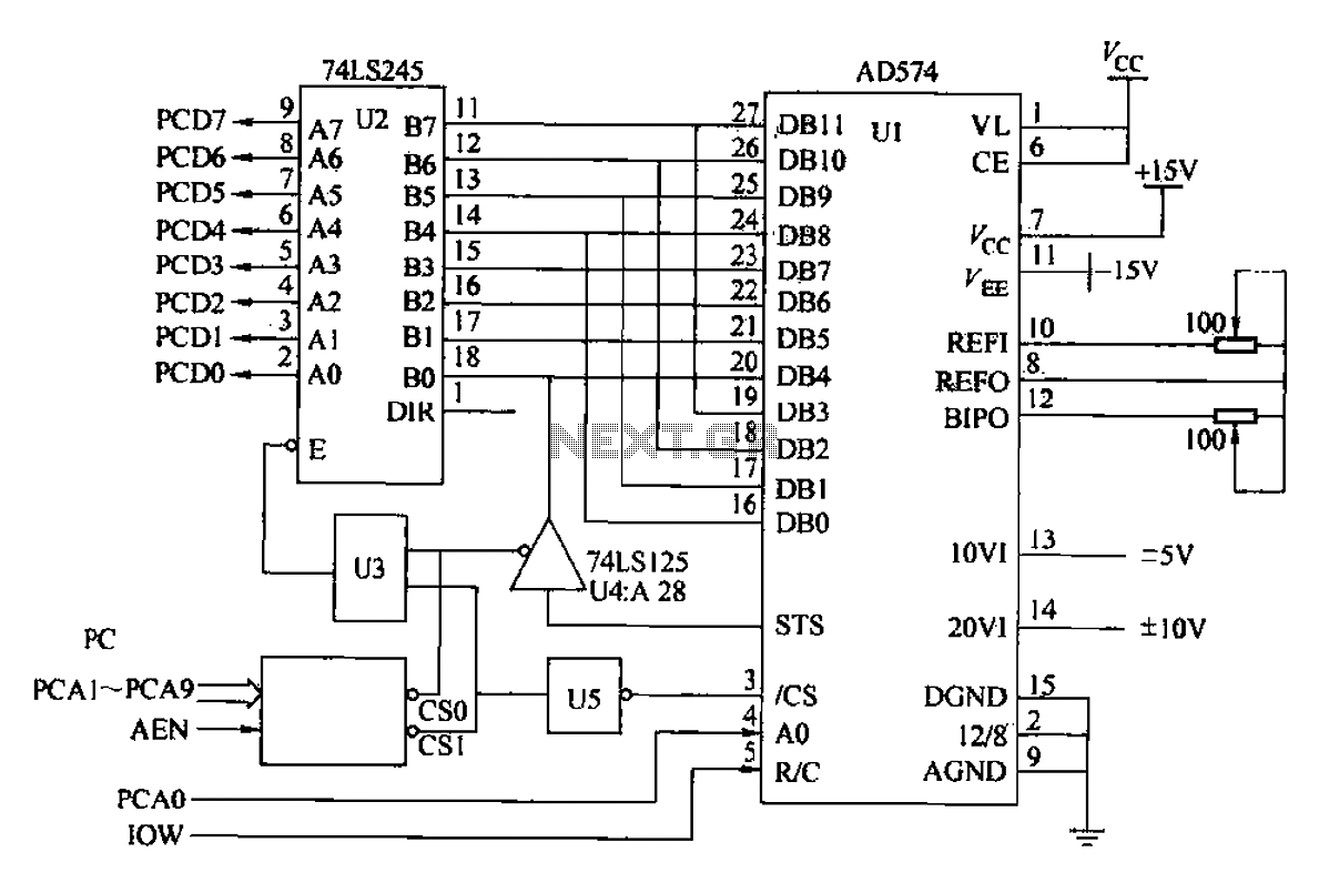
Another example is provided using the AD574 and PC bus. The AD574 converter is represented by U1, while U2 is a 74LS245 bidirectional data buffer. U3 is a 74LS00 two-input AND gate, U4 is a 74LS125 tri-state output gate,...
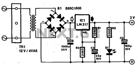
Most small portable radios require a 3-V supply, which is typically provided by two AA or AAA batteries. Many of these radios are equipped with a charger socket since rechargeable batteries are an option. When used in a stationary...
This circuit provides a straightforward and efficient method for interfacing two relays in switching applications. The relay driver utilizes a standard BC547 NPN transistor (or equivalent) to enhance the input impedance. It is a widely used driver capable of...
The simple relay adder was constructed using free NOS relays around 2005, with the intention of eventually creating a more complex version capable of running programs without occupying a large space like early computers. An impressive 415-relay computer was...
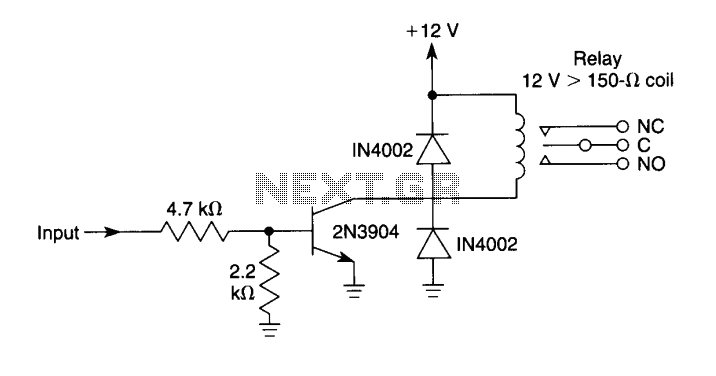
This circuit can be used to drive a 12V relay with a triggering signal of 5V. It incorporates two 1N4002 diodes, one 2N3904 transistor, and two resistors. By altering the resistor values, the input triggering voltage can be modified. The...