
Parallel Port Stepper Motor Driver With Discrete Components

The described circuit employs a parallel port to interface with a unipolar stepper motor through discrete MOSFETs, providing an effective means of control. The use of the ULN2003 Darlington driver is a common practice, but the implementation of MOSFETs can offer advantages in terms of efficiency and heat management. The MITSUMI M35SP-9 serves as a suitable example for this application, as it demonstrates the capabilities of the circuit with its standard unipolar configuration.
In the schematic, the four power MOSFETs are arranged to control the four coils of the stepper motor. Each MOSFET's gate is connected to a data pin on the parallel port, allowing for direct control of the motor's phases. The pull-down resistors are essential for ensuring that the gates of the MOSFETs remain in a known state when not actively driven by the parallel port, thereby preventing false triggering due to noise or interference.
The C code provided is integral to the operation of the stepper motor driver. By setting the data port pins to high in a specific order, the motor is commanded to step in a clockwise direction. The ability to reverse the motor's direction by simply altering the output sequence exemplifies the flexibility of this design. This approach allows for straightforward integration into various applications where precise motor control is required, such as robotics, CNC machines, or automated systems.
Overall, this circuit offers a practical and efficient solution for controlling unipolar stepper motors using a PC's parallel port, with the potential for further modifications and enhancements to suit specific project requirements.Using PC`s parallel port is a convenient way to control a stepper motor. For unipolar stepper motors, up to two motors can be controlled with the 8bit data line. The standard way of connecting a unipolar stepper motor to the parallel port is to use a Darlington driver such as ULN2003 and there are already many examples out there on how to do this. In this post, I will show you how to build a simple stepper motor driver using discrete MOSFET s. In the circuit diagram below, you will find that the four power MOSFETs are used as switches for each coil in the stepper motor (the stepper motor I used in this example is a MITSUMI M35SP-9. In theory, any uni-polar stepper motors should work with this circuit). A pull-down resistor is attached to the gate of each MOSFET. This is important as otherwise the interference from the port would prevent the MOSFET from switching reliably.
The following C code sets the data port (pin 2, 3, 4, 5) to high in order so that the stepper motor would rotate clockwise. If you want the motor to rotate counter-clockwise, simply change the output order to 8, 4, 2, 1. 🔗 External reference
Related Circuits
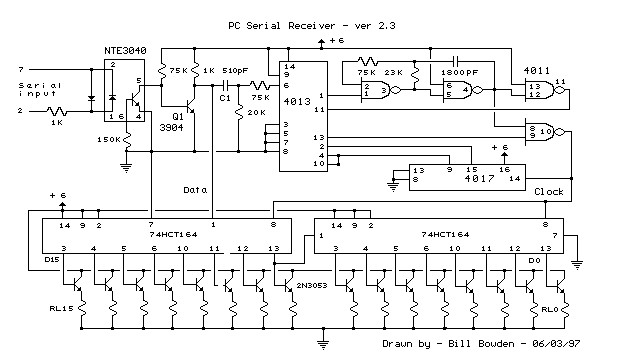
This circuit requires physical connections to be made to the computer's serial port (COM1 or COM2). It is generally considered difficult to cause harm to oneself or the computer through improper connections to this port; however, there is no...
The 3D printer necessitates independent control for three separate axes. Each controlled axis must be equipped with a high-precision electronic driver. The mechanical components of each axis utilize a precise bipolar stepper motor connected to a drive shaft via...
A dual benefit for battery-powered portable devices is provided by Class D audio amplifiers. They produce much less power dissipation than their linear counterparts. Class D audio amplifiers, also known as switching amplifiers, are designed to achieve high efficiency and...
The LWDAQ Driver (A2037) is a Long-Wire Data Acquisition (LWDAQ) Driver. An introduction to the LWDAQ can be found in the LWDAQ User Manual. The A2037 features eight LWDAQ driver sockets, which can be connected to either a LWDAQ...
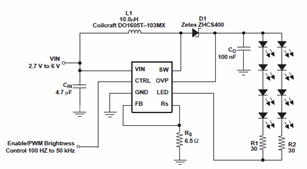
The schematic diagrams for the TPS61042 current LED driver illustrate its capability to power eight LEDs with an efficiency of 81% at 3.6V and 18.6mA. The TPS61042 is commonly utilized in applications such as white LED supply for backlight...
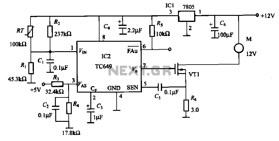
A motor is a heating device that can overheat, often due to accidents or overloads caused by excessive coil winding temperatures. The TC649 motor overheating protection and drive circuit, depicted in FIG. 1-9, utilizes an NTC thermistor (RT) positioned...