
The PC Serial Port Receiver circuit

The circuit utilizes the computer's serial port, which is a standard interface for communication between the computer and peripheral devices. The serial port operates using a set of pins that transmit data in a sequential manner, typically employing the RS-232 standard. This standard defines the voltage levels and signal timing necessary for communication.
When connecting to the serial port, it is essential to identify the correct pins for transmission (TX) and reception (RX). The TX pin transmits data from the computer to the device, while the RX pin receives data from the device to the computer. In a typical DB9 connector, TX is usually on pin 3, and RX is on pin 2. Additionally, there may be ground (GND) connections required, typically found on pin 5.
To ensure the circuit functions correctly, it is advisable to use appropriate voltage levels. The RS-232 standard specifies that logic high levels should range from +3 to +15 volts, while logic low levels should range from -3 to -15 volts. It is crucial to use a level shifter if the connected device operates at TTL (Transistor-Transistor Logic) levels, typically 0 to 5 volts, to prevent damage to the computer's serial port.
In designing the circuit, attention must be paid to the configuration of the serial communication settings, including baud rate, parity, data bits, and stop bits. These settings must be consistent between the computer and the connected device to facilitate successful data exchange.
Proper shielding and grounding techniques should be employed to minimize electromagnetic interference (EMI) that could disrupt signal integrity. Additionally, ensuring that the connections are secure and insulated can prevent accidental shorts or disconnections during operation.
Overall, while the risk of damage is low when connecting to a serial port, exercising caution and adhering to proper electrical practices is essential to safeguard both the computer and the connected devices.This circuit requires physical connections be made to the computer`s serial port (COM1 or 2). To the best of my knowledge, it is difficult to cause damage to yourself or your computer by improper connections to this port, but there is no guarantee that damage will not result. Use caution when making any external electrical connections. 🔗 External reference
Related Circuits

Figure 1-30 illustrates an example of an output capacitor-less (OCL) power amplifier circuit, which can be analyzed as follows: In this circuit, transistors VTi and VTz form a single-ended input and a differential input single-ended output amplifier configuration. The...
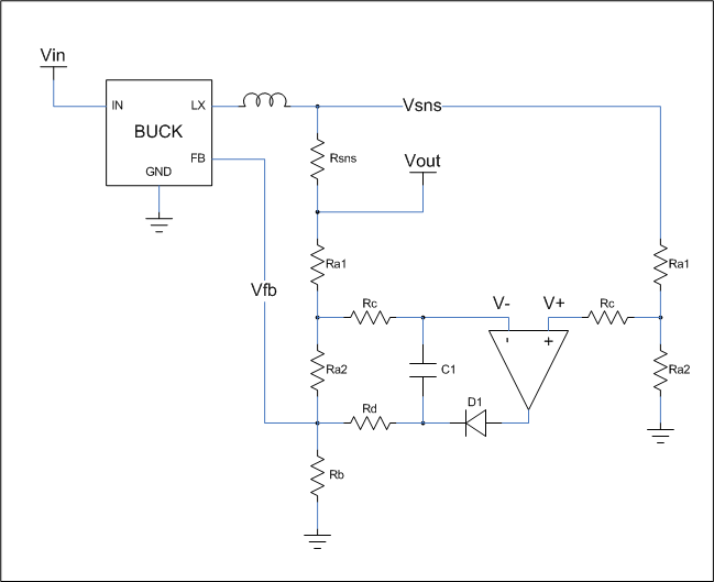
This is a cost-effective circuit that incorporates precise current limiting functionality into a voltage regulator. The circuit described is designed to enhance the performance of a voltage regulator by integrating a current limiting feature. This is particularly beneficial in applications...
This is a simple electronic siren circuit that can be utilized in various applications where a siren sound is necessary. The circuit is straightforward, employing only two transistors and a few additional components, and it will produce a siren...

The schematic for the board is illustrated below. The three primary components of the board include (1) the power input and voltage regulation, (2) the L297 input and outputs, and (3) the L298 stepper motor control circuit. The motor...
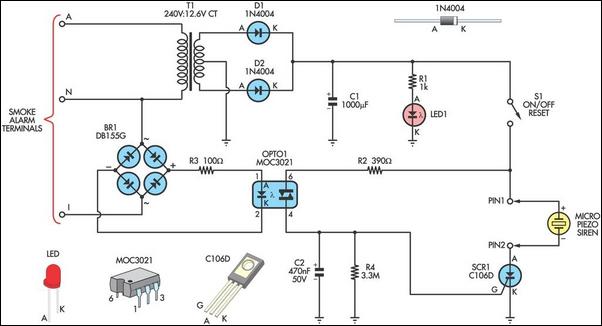
This alarm circuit is designed to monitor a mains-powered smoke detector located in a shed used for dog kennels. It ensures complete isolation from the mains, allowing low-voltage (12V) cabling to connect to the alarm circuit situated inside the...
The input signal is applied to a gate G and then to a counter for a precise period of time. After this period, the input signal is stopped for a while, and then the cycle is repeated. During the...