
PC Fan Controller Circuit

This PC fan controller circuit utilizes a combination of discrete components to effectively manage the operation of 12V DC fans, particularly those with a current draw not exceeding 200mA. The circuit ensures stable operation by preventing the voltage from dropping below 7V, which is crucial for maintaining fan performance.
The core of the circuit is built around two transistors, T1 and T2, which function as a comparator. These transistors compare the fixed voltage derived from resistors R3 and R4 against a temperature-dependent voltage generated by resistors R1 and R2. This configuration allows for precise control over the fan speed based on the ambient temperature, as sensed by the KTY10 temperature sensor.
In scenarios where the fan does not start at lower temperatures (e.g., 25°C), a temporary workaround involves replacing the temperature sensor with a fixed resistor (1.8kΩ) to bypass the temperature dependency. Additionally, adjustments to resistor R7 can calibrate the fan's operational speed; increasing R7 will reduce the fan speed, while decreasing it will allow for higher speeds.
For further fine-tuning, it is advisable to incorporate a 25kΩ potentiometer in place of R2. This allows for real-time adjustments to the temperature threshold at which the fan begins to operate. Once the desired setting is achieved, the potentiometer's resistance can be measured and replaced with a fixed resistor of equivalent value, ensuring stability in operation.
The placement of the temperature sensor is critical; it should be positioned in the warm air stream of the fan to accurately gauge the temperature. Initially, when the PC is powered on, the fan may operate at a high speed due to the charging of capacitor C1. However, as the system stabilizes, the fan speed will decrease to a minimum operational level.
The controller is designed to activate at a threshold temperature of 35°C. If the fan does not respond as expected, adjustments to R2 or the potentiometer can be made to modify the activation point. As the temperature rises, the fan speed will correspondingly increase, though it is important to note that the maximum speed will be inherently limited compared to a configuration without the control circuit. This design not only enhances the efficiency of the cooling system but also contributes to reduced noise levels and improved thermal management within the PC environment.This PC fan controller circuit is designed with discrete components and is used to control 12 V fans that have a current consumption lower than 200mA. With the components values presented in the circuit diagram, the voltage won`t drop below 7V. If the fan won`t start at 25 °C then temporarily replace the temperature sensor KTY10 with a 1. 8k © resi stor and reduce the value of R7. If the PC fan has a speed too high then increase the R7 value. T1 and T2 transistors compare the fixed potentional from R3-R4 common point with the temperature dependent potentional of R1-R2 common point. It may be useful to connect a 25k © potentiometer instead of R2 and to adjust it until the PC fan is at the correct speed and to measure its resistance and then replace it with a fix resistor with the same value.
Place the temperature sensor in the warm air of the fan. When the PC is connected the speed rotation of the fan will be pretty high because of C1 but will decrease at a minimum value. Measure with a thermometer the air temperature close to the sensor. When the temperature reaches 35 °C the controller circuit will start to work. If this won`t happen modify the value of R2 or adjust a potentiometer placed instead of R2. When the temperature increases so will the rotation speed of the PC fan. The maximum speed will be lower than the one obtained without the control circuit. 🔗 External reference
Related Circuits
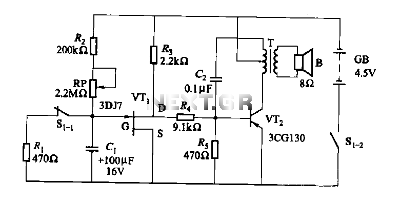
The darkroom circuit is designed for one-time exposure and emits an audible signal when the developing time is reached. This circuit can be utilized for photofinishing large timers and other applications. It comprises components such as FET VTi, resistors,...
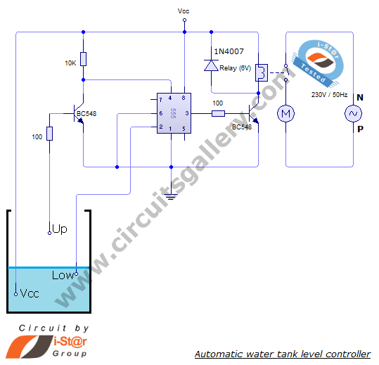
The automatic water level controller circuit is a straightforward engineering project that can automatically switch a domestic water pump on and off based on the water level in a tank. This motor driver circuit can be implemented at home...

The thermistor RT, along with resistors R1, R2, R3, and variable resistor RP1, creates a temperature measurement bridge. At a temperature of 20°C, the configuration of R1, R3, and the adjustment of RP1 enables the bridge to maintain balance....
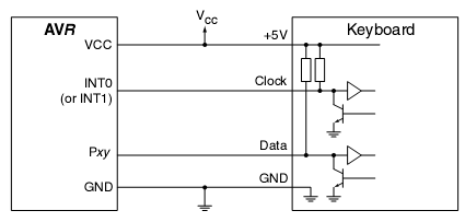
In many situations, a human interface is required for microcontroller projects. This example describes the interfacing of an AVR microcontroller with a standard PC AT keyboard. According to the keyboard timing diagram, the keyboard transfers data to the host...
Designs for audio amplifiers with DC coupling to the load are not frequently seen today, despite offering distinct advantages. Audio amplifiers that employ DC coupling to the load provide several benefits that can enhance performance in specific applications. In traditional...
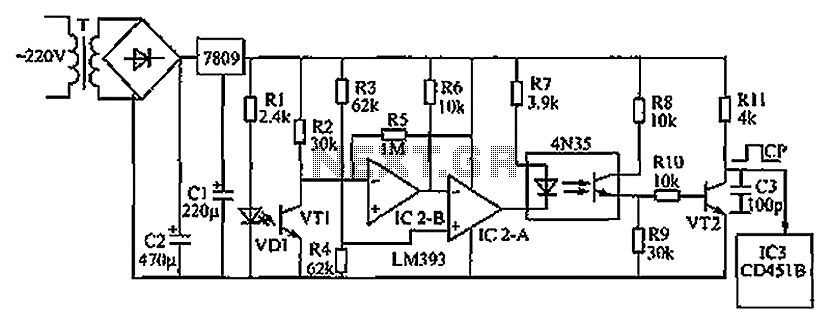
The circuit depicted in the figure operates as follows: when the phototransistor VT1 detects infrared light emitted by the infrared light-emitting diode, it enters a conductive state. This action causes the inverting input of comparator IC2-B, connected to pin...