
Percussion electronic doorbell 1

The electronic doorbell circuit provides a comprehensive solution for generating sound alerts upon activation. The pickup amplifier captures the sound of the doorbell press using a piezoelectric ceramic element, which converts mechanical vibrations into electrical signals. This signal is then amplified by the amplification tube, ensuring sufficient strength for further processing.
The monostable trigger circuit is activated by the amplified signal from the pickup amplifier. It generates a single output pulse of a predetermined duration, which is essential for timing control in the circuit. This pulse is fed into the pulse counter circuit, which counts the number of activations. This feature allows for multiple doorbell presses to be registered and can be configured to trigger different responses based on the count.
The music generating circuit utilizes a series of oscillators and sound synthesis components to produce musical tones or melodies. This circuit is crucial for providing a pleasant auditory feedback to the user, enhancing the overall experience of the doorbell system. The output from the music generating circuit is then fed into the audio amplifier circuit, which boosts the signal to drive a speaker or buzzer, ensuring that the sound produced is loud enough to be heard clearly.
Overall, the electronic doorbell circuit integrates various components to deliver a reliable and effective doorbell solution, combining sound generation with user interaction. Each section of the circuit plays a vital role in ensuring the system operates smoothly and efficiently.The electronic doorbell circuit is composed of the pickup amplifier, monostable trigger circuit, pulse counter circuit, music generating circuit and audio amplifier circuit and other components, and it is shown in Figure 3-113. Pickup amplifier circuit consists of piezoelectric ceramic BC, amplification tube Vl, resistors Rl and R2 and capacitor Cl and so on..
🔗 External reference
Related Circuits
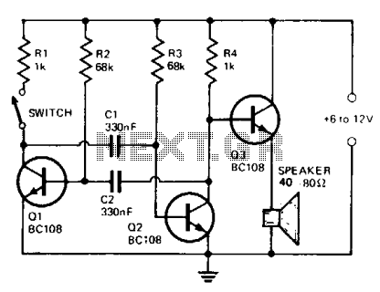
The circuit comprises a multivibrator (Q1 and Q2) and a low-power output stage (Q3). The speaker should have an impedance ranging from 40 to 80 ohms. To accommodate a low-impedance speaker, an output transformer should be connected from the...
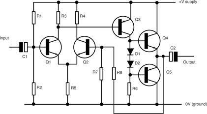
The term amplifier, as used in this article, can refer to either a circuit (or stage) utilizing a single active device or a complete system such as a packaged audio hi-fi amplifier. An electronic amplifier is a device designed...
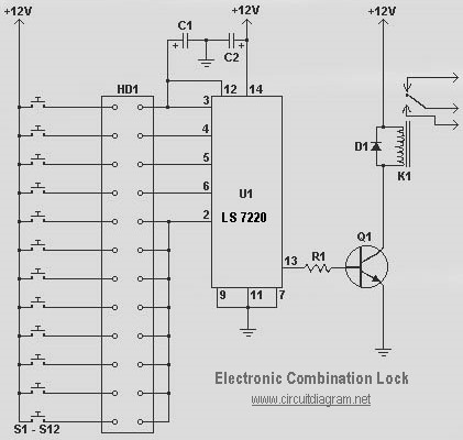
The following diagram illustrates a simple electronic combination lock based on the IC LS7220. The component part list includes: C1 = 1µF 25V, C2 = 220µF 25V, R1 = 2.2K Ohm, Q1 = 2N3904 or 2N2222, D1 = 1N4148...
This motor starter safeguards single-phase motors from voltage fluctuations and overloads. A key feature is the soft on/off electronic switch, which facilitates user operation. The transformer reduces the AC voltage from 230V to 15V. Diodes D1 and D2 convert...

This electronic circuit, based on the CD4017 and logic gates, activates a relay when four keys are pressed in the correct sequence, returning to the initial state afterward. The circuit utilizes the CD4017 decade counter, which is designed to count...
Electronic Schematic Circuit Diagrams Manual PDF Download. The document provides a comprehensive manual that focuses on electronic schematic circuit diagrams. These diagrams are essential tools for understanding and designing electronic circuits, offering visual representations of circuit components and their interconnections....