
Periodic Timer

The timer circuit employs a 7555 timer IC, which is a variant of the standard 555 timer, designed for low power applications. This circuit is configured to operate in astable mode, generating a continuous square wave output with adjustable duty cycle and frequency. The unique feature of this timer is its ability to maintain the timing sequence indefinitely when switch S1 is engaged, allowing for prolonged operation until manually interrupted.
The timing component consists of a resistor network (R1 to R6) and a capacitor (C1). The 6-way rotary switch S3 allows for variable resistance to be introduced into the circuit, effectively altering the timing characteristics. Each position of the switch corresponds to a different resistance value, thus modifying the total resistance in series with the capacitor, which in turn affects the charge and discharge time of C1.
The timing duration is calculated using the formula T = 1.4 R1 C1, where T represents the total time period for one complete cycle of the output waveform. This formula indicates that the output frequency and duty cycle can be adjusted by changing either the resistance values or the capacitance of C1. A low leakage capacitor is essential to ensure accurate timing, as any leakage could result in timing inaccuracies.
The output pulse, which can be observed at pin 3 of the 7555 timer, can be utilized to drive various loads, or it can be fed back into a control circuit for further processing. The timer can be used in applications requiring precise timing intervals, such as in automated systems, delay circuits, or as a timer for various electronic devices. The design is robust and can be easily modified to suit different timing requirements by altering the resistor values or the capacitance of C1.A switched timer with equal make and equal space periods timing adjustable from over 6 minutes to 38 minutes. This timer circuit is similar to the 5 to 30 minute timer except that when switch S1 is closed, the on/off action of the circuit will continue indefinately until S1 is opened again.
A 7555 time and low leakage type capacitor for C1 must be used. The 6 way rotary switch S3 adds extra resistance in series to the timing chain with each rotation, minimum resistance point "a" maximum point "f". The 7555 is wired as an equal mark/space ratio oscillator, the timing resistor chain R1 to R6, being connected back to the output of the timer at pin 3.The output pulse duration is defined as:- T = 1.4 R1 C1 This gives on and off times of about 37 🔗 External reference
Related Circuits
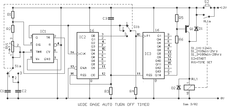
A wide range auto turn OFF timer covering 1 minute to 20 hours in three ranges with S1. As soon as power is applied to the circuit, the IC1 [555] starts to oscillate and feeds clock pulses to the...
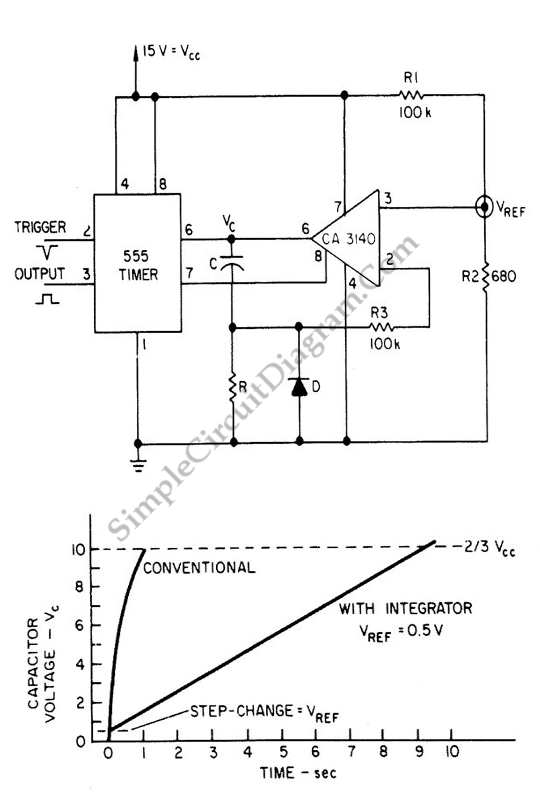
The 555 IC is a widely used component for timer circuits. By incorporating an integrator circuit, it is possible to extend the timing period of the 555 IC timer while maintaining a reasonable capacitor size. The 555 timer IC is...
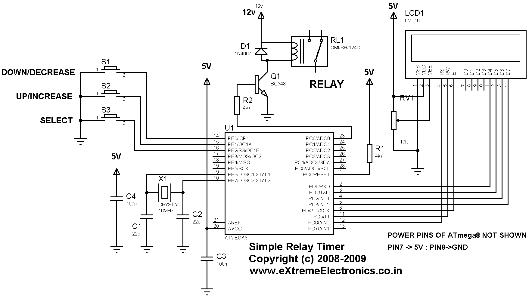
A simple timer that can be used to turn a load on or off after a user-specified time. The prototype was developed using the xBoard MINI, a low-cost and easy-to-use ATmega8 development board. The program was burned to the...
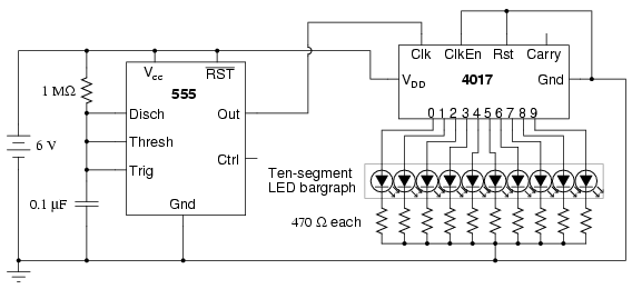
The following circuit illustrates a schematic diagram of an LED sequencer. This circuit is based on the 555 timer integrated circuit (IC). Features include a 555 timer circuit designed to debounce a mechanical switch, a 555 timer circuit to...

A project is underway that necessitates the conversion of a 0-10V DC supply into a linear frequency range in the form of a square wave. The project involves designing a circuit that takes a direct current (DC) voltage input ranging...
To achieve a lower parts count than the two-transistor multivibrators, two LEDs can be alternately flashed using a 555 integrated circuit configured as illustrated in Schematic 2. A combination of a 2.2kΩ and a 47kΩ resistor is used to...