
transceiver circuits

To operate, apply 13.8 Volts to the rear connector, connect the antenna, and attach the microphone. Set all controls to maximum counterclockwise and toggle the switches to OFF (up). The DTMF / HL / Tone Switch should be set to "HL". Advance the Receiver AF gain slightly and rotate the Receiver SQL control until noise is audible. Adjust the AF gain to a convenient level and set the SQL for the muting threshold. Increase the MIC gain and speak into the microphone without activating the PTT or TRANSMIT key; the microphone audio level should be indicated on the VU meter. Adjust the MIC gain so that at the speaking level and distance, the VU meter deflects to the reference level (0 VU) on frequent peaks. To test audio on the HL input, select HL on the MIC/HL switch; the HL audio should be indicated on the VU meter as the HL gain is advanced. Set the HL level for reference deflection on the VU meter. For listening to the applied audio without transmitting, insert PHONES into the front panel jack or use the internal or extension speaker, selecting AF IN. The audio from either MIC or HL can be heard, depending on the selection (note that MIC audio is muted if the internal or external SPEAKER is in use).
Select PK DEV on the VU/PK DEV meter switch to display the relative peak deviation level of any received signal on the level meter. A deviation of +/-5KHz corresponds approximately to 100% on the level meter. Reselect VU. To transmit, either press the locking TRANSMIT key or use the microphone PTT. The RF meter will deflect to about 70% of full scale, indicating relative transmitter RF output (no Receive RF level indication is provided in the prototype units). The actual transmitter power output is approximately 15 watts, depending on the power supply regulation, with a total power drain of about 5 Amps during transmission. The transmit frequency is 146.100 MHz with CH 2 selected; with AUX selected, transmit and receive frequencies will depend on the chosen crystals.
With TRANSMIT activated, select HL on the MIC/HL switch and TONE on. The VU meter should deflect to the reference level, producing a relatively low distortion continuous 1000 Hz tone. This tone can be keyed by inserting a key or keying contact in the rear panel jack, which operates a reed relay carrying a current of about 10mA from 13.8 volts. A simple contact closure or an open collector NPN transistor switch is required for keying. With TRANSMIT and TONE selected, turn MON on to activate the receiver on the TRANSMIT frequency, allowing the transmitted tone to be heard in the headphones or speaker.The unit is based on a PHILIPS FM880 link transceiver which was originally supplied to a Telecom Australia specification for telephone applications in remote areas of Australia. The FM880 in turn is part of the family of equipment including the PHILIPS FM828/FM814 series of fixed and mobile transceivers.
The main receiver and transmitter exciter b oards are identical in most cases and are surrounded with specialized boards and circuitry for the particular application. The VK6WIA modifications are therefore simply another variant of the versatile PHILIPS design, although a fundamental change has been made in that the system of modulation has been changed to direct FM of the exciter reference crystal oscillator.
The inbuilt phase modulator on the original FM880 exciter board is unused. Other audio, power supply and control facilities have been added to provide the WIA Broadcast Officer with a transceiver designed to provide the regular news broadcast service. Extracts from the FM880 handbook, detailing receiver and transmitter circuit description, alignment instructions, circuit diagrams and board layouts are attached at Appendix I.
4. 1. Apply 13. 8 Volts to rear connector, connect antenna and attach microphone. Set all controls to max anticlockwise and toqqle switches to OFF (up). The DTMF / HL / Tone Switch should be on "HL". 4. 3. Advance Receiver AF gain by a small amount. Rotate Receiver SQL control until noise is heard. Set AF gain for a convenient level and adjust SQL for muting threshold. 4. 5. Advance the MIC gain and speak into the microphone without activating the PTT or TRANSMIT key. The microphone audio level should indicate on the VU meter. Set the MIC gain so that at the speaking level and distance to be used the VU meter on frequent peaks deflects to reference level (0 VU) 4. 6. Apply test audio on the HL input. Select HL on the MIC/HL switch. The HL audio should indicate on the VU meter as the HL gain is advanced. Set the HL level for reference deflection on the VU meter. 4. 7. If it is desired to listen to the audio applied so far, without transmitting, insert PHONES into the front panel jack, or use the internal or extension speaker.
Select AF IN. The audio from MIC or HL can now be heard depending on which is selected. (However the MIC audio is muted if the internal or external SPEAKER is in use). 4. 9. Select PK DEV on the VU/PK DEV meter switch. The relative peak deviation level of any received signal will be displayed on the level meter. +/-5KHz deviation corresponds approximately to 100% on the level meter. (This indicated level is after de-emphasis so is not a true deviation measurement on speech, but is calibrated for a single tone of 1000Hz). Reselect VU. 4. 10. To transmit, either press the locking TRANSMIT key or use the microphone PTT. The RF meter will deflect to about 70% of full scale, providing a relative indication of transmitter RF output.
(No Receive RF level indication is provided in the prototype units). Actual transmitter power output is about 15 watts, depending to some extent on the regulation of the power supply. Total power drain on transmit is about 5 Amps. The transmit frequency is 146. 100 MHz, with CH 2 selected. With AUX selected, transmit and receive frequencies will depend on chosen crystals. 4. 11. With TRANSMIT activated, select HL on the MIC/HL switch and TONE on. The VU meter should deflect to reference level, providing a relatively low distortion 1000 Hz continuous tone.
The tone can be keyed by inserting a key or keying contact in the rear panel jack. The key operates a reed relay and carries a current of about 10mA from 13. 8 volts. Simple contact closure or an open collector NPN transistor switch is required to key. 4. 12. Still with TRANSMIT and TONE selected, select MON on. The receiver will be activated on the TRANSMIT frequency and the transmitted tone will be heard in the phones or speaker. That is, OFF 🔗 External reference
Related Circuits

The circuit employs a field-effect transistor (FET) at the input of a Schmitt trigger, allowing the use of a low-value capacitor. The trigger, controlled by Q1 and O2, exhibits a hysteresis of approximately 3V, regulated by a 3V zener...
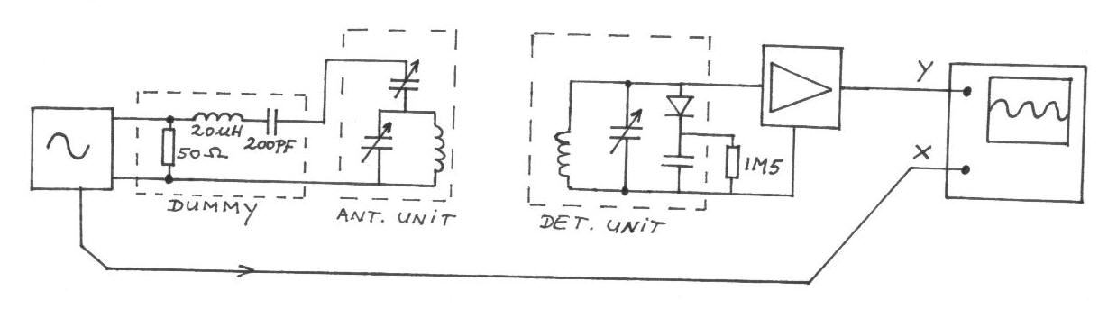
The frequency remains constant, oscillating between two predetermined values. On the oscilloscope display, a frequency spectrum is observed, showcasing the response curves of the two circuits. The input voltage of the receiver is 0.1 Volt peak-to-peak, while the voltage...
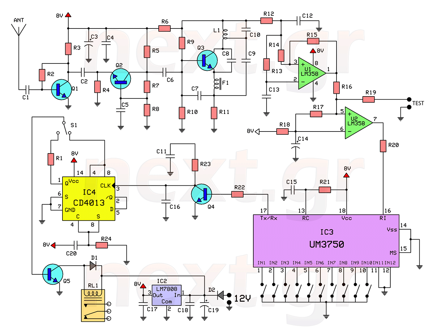
This circuit includes a 2048 radio remote control transmitter and a corresponding wireless receiver that features high reception sensitivity and low power consumption. The combination of these two components provides a highly reliable remote control system, suitable for various...
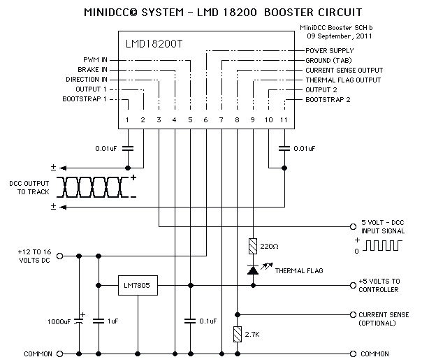
These circuits could be used as the basis for Model Railroad DCC Boosters or PWM motor controllers. The first schematic is for a basic 3 Amp - DCC Booster using the LMD 18200 CMOS, H-Bridge. Included in the design...
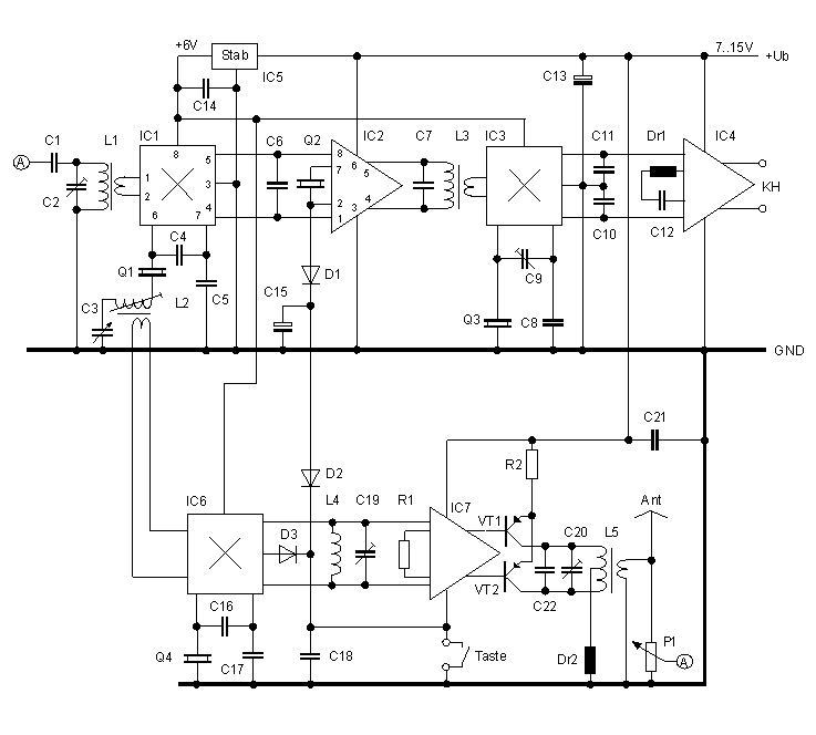
This simple QRP transceiver for the 30 m band did not result from a detailed requirement profile. I simply had some NE592 broadband amplifiers in my junk box, waiting for an application. After performing some tests, that application was...
This subwoofer filter set is suitable for use with a high-quality car audio system. The circuit is designed to operate with a 12-volt DC power supply. The subwoofer filter set serves as an essential component in enhancing the audio experience...