Valve audio headphones Amplifier
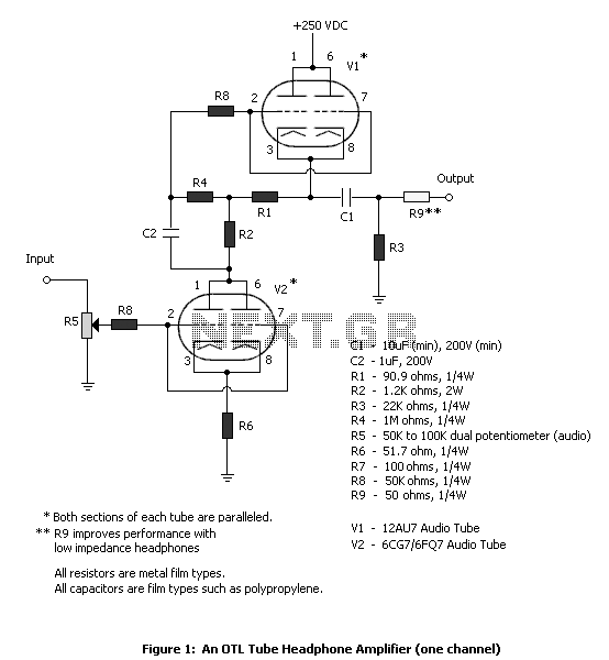
The tube headphone amplifier in figure 1 is a high current mu follower, with a 12AU7 cathode follower driven by a 6CG7. Both sections of each tube are paralleled to minimize noise. It's a zero global feedback, OTL design of pretty high quality. I use it and like it for Grado, Sennheiser, and Sony headphones. The maximum gain is about 25 dB with the 6CG7, so it pays to watch the attenuator level. This design can be used as a line preamp as well. The power output depends a lot on headphone impedance. The circuit has significant output impedance (something like 500 ohms) which some headphones don't mind, some do. It will put out around 20 mA peak current. The output impedance is pretty much constant and independent of load, but any tube changes will greatly affect it. It runs off a 330V supply, which necessitated changing R2 to 5.6K ohms, 2W. The 6VDC filament supply is regulated with 7806 regulators. All instructions, including a chassis drilling guide and parts layout, can be found at http://home.online.no/~wsaa/otl/otl.html. Revised volume control in figure 1. The OTL is now fully tweaked and working beautifully. In fact after the conversion to DC heaters it was MUCH MORE STABLE! I have been experimenting with 3 different front end tubes. The 6CG7, 6FQ7 and my favorite, the Svetlana 6N1P. The GE 6CG7's with "white" logo seen second best in terms of level and sound quality. The 6N1P's are really much better though; they are much less muddy than the 6CG7's, have better low end, better imaging and much more transparent. Also an added benefit of their 300ma heaters is they glow quit nicely! Eduard Orvisky built this headphone amplifier using ideas from Kurt Strain's and Eric Barbour's designs. It uses two 6SN7s in the mu follower (compared to Eric Barbour's circuit, R4 is reduced to 2K, 2W) and solid state and rectified heaters (he also tried a 5Y3 tube rectified supply, but preferred the solid state version for its faster sound). The chassis for this prototype was made from a sheet of plexiglass. It has no bottom, and permits quick substitution of parts. Layout is crucial to avoid motorboat oscillation due to parallel operation. Short wires across tube pins help this, and have them cross each other perpendicularly. Once the oscillation is gone, it stays gone. If this problem persists, separate cathode resistor R7 into 2 cathode resistors, 100 ohms each to ground, and add 100 ohm plate resistors to V1 on each side, to B+. This will isolate the mismatch between units better and prevent a bistable bias condition. Both channels run off a well-filtered 6VDC, 2.5A filament supply and a 250VDC supply with separate filter capacitors for each channel to minimize hum and crosstalk. The supplies don't need to be regulated. The 12AU7 will take the raised cathode potential so you don't need to raise the voltage of the filament supply above ground level. The Hammond 269EX power transformer works very well in this application and can be obtained from Angela Instruments. Use shielded twin lead to wire the filaments. Run one lead to each tube separately from the transformer to keep current on the line at a minimum. Keep the filament wire away from the signal and DC power supply wires. Also, keep the power supply away from the amplifier circuit, especially V2.
The described tube headphone amplifier employs a high current mu follower configuration, utilizing a 12AU7 as a cathode follower driven by a 6CG7 tube. This configuration is designed to minimize noise by paralleling both sections of each tube. The amplifier operates on a zero global feedback, output transformerless (OTL) design, which is noted for its high sound quality. This amplifier is particularly suitable for driving headphones from brands such as Grado, Sennheiser, and Sony, with a maximum gain of approximately 25 dB provided by the 6CG7 tube. Care should be taken with the attenuator level to prevent distortion at higher gains.
The amplifier's power output is significantly influenced by the impedance of the connected headphones, with an output impedance estimated at around 500 ohms. This characteristic may affect compatibility with certain headphone models, as it is relatively high. The circuit is capable of delivering up to 20 mA of peak current, with the output impedance remaining largely constant regardless of the load, although variations in tube types can lead to changes in performance.
Powering the amplifier requires a 330V supply, necessitating a modification of resistor R2 to a 5.6K ohm, 2W rating. The filament supply operates at 6V DC and is regulated using 7806 voltage regulators, ensuring stable operation. Detailed assembly instructions, including a chassis drilling guide and parts layout, are available online.
The design incorporates a revision of the volume control for improved usability. The stability of the amplifier has been enhanced through the conversion to DC heaters, which has been positively noted in user feedback. Various front-end tubes, such as the 6CG7, 6FQ7, and Svetlana 6N1P, have been tested, with the latter providing superior audio performance characterized by clarity and enhanced low-frequency response.
The amplifier's construction emphasizes the importance of layout to avoid issues such as motorboat oscillation, particularly in parallel tube configurations. To mitigate this, short wire connections across tube pins are recommended, with wires crossing perpendicularly to each other. In cases of persistent oscillation, it is advisable to split the cathode resistor R7 into two 100-ohm resistors grounded separately and to add 100-ohm plate resistors to the first tube on each side, improving isolation between units.
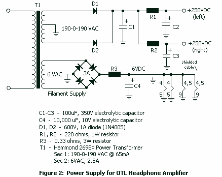
Both channels of the amplifier utilize a well-filtered 6VDC, 2.5A filament supply and a 250VDC supply, each channel having its own filter capacitors to reduce hum and crosstalk. The design does not require regulation for the supplies, as the 12AU7 can handle raised cathode potentials without necessitating an elevated filament supply voltage. The Hammond 269EX power transformer is recommended as an effective component for this application.
For optimal performance, shielded twin lead wires should be used to connect the filaments, ensuring that each tube receives a separate lead from the transformer to minimize current on the line. It is also critical to maintain distance between filament wiring and signal or DC power supply wiring, as well as keeping the power supply physically separated from the amplifier circuit, particularly from the second tube.The tube headphone amplifier in figure 1 is a high current mu follower, with a 12AU7 cathode follower driven by a 6CG7. Both sections of each tube are paralleled to minimize noise. It's a zero global feedback, OTL design of pretty high quality. I use it and like it for Grado, Sennheiser, and Sony headphones. The maximum gain is about 25 dB with the 6CG7, so it pays to watch the attenuator level. This design can be used as a line preamp as well. The power output depends a lot on headphone impedance. The circuit has significant output impedance (something like 500 ohms) which some headphones don't mind, some do. It will put out around 20 mA peak current. The output impedance is pretty much constant and independent of load, but any tube changes will greatly affect it.
It runs off a 330V supply, which necessitated changing R2 to 5.6K ohms, 2W. The 6VDC filament supply is regulated with 7806 regulators. All instructions, including a chassis drilling guide and parts layout, can be found at http://home.online.no/~wsaa/otl/otl.html. 7/16/99: Revised volume control in figure 1. 1/14/00: Jason Portman writes: The OTL is now fully tweaked and working beautifully. In fact after the conversion to DC heaters it was MUCH MORE STABLE! I have been experimenting with 3 different front end tubes. The 6CG7, 6FQ7 and my favorite, the Svetlana 6N1P. The GE 6CG7's with "white" logo seen second best in terms of level and sound quality. The 6N1P's are really much better though; they are much less muddy than the 6CG7's, have better low end, better imaging and much more transparent.
Also an added benefit of their 300ma heaters is they glow quit nicely! 7/15/00: Eduard Orvisky built this headphone amplifier using ideas from Kurt Strain's and Eric Barbour's designs. It uses two 6SN7s in the mu follower (compared to Eric Barbour's circuit, R4 is reduced to 2K, 2W) and solid state and rectified heaters (he also tried a 5Y3 tube rectified supply, but preferred the solid state version for its faster sound).
The chassis for this prototype was made from a sheet of plexiglass. It has no bottom, and permits quick substitution of parts. Layout is crucial to avoid motorboat oscillation due to parallel operation. Short wires across tube pins help this, and have them cross each other perpendicularly. Once the oscillation is gone, it stays gone. If this problem persists, separate cathode resistor R7 into 2 cathode resistors, 100 ohms each to ground, and add 100 ohm plate resistors to V1 on each side, to B+. This will isolate the mismatch between units better and prevent a bistable bias condition. Both channels run off a well-filtered 6VDC, 2.5A filament supply and a 250VDC supply with separate filter capacitors for each channel to minimize hum and crosstalk (figure 2).
The supplies don't need to be regulated. The 12AU7 will take the raised cathode potential so you don't need to raise the voltage of the filament supply above ground level. The Hammond 269EX power transformer works very well in this application and can be obtained from Angela Instruments.
Use shielded twin lead to wire the filaments. Run one lead to each tube separately from the transformer to keep current on the line at a minimum. Keep the filament wire away from the signal and DC power supply wires. Also, keep the power supply away from the amplifier circuit, especially V2. 🔗 External reference
