
Audio high-pass filter

The high-pass filter depicted in Figure 1-102 serves to allow signals with a frequency higher than a certain cutoff frequency to pass through while attenuating signals with frequencies lower than the cutoff. The configuration in part (A) demonstrates a scenario where capacitor values C1 and C2 are equal, and resistor R1 is set to half the value. This results in a specific crossover frequency, calculated as fH = 1/(2√(2R1C1)). This equation indicates that the cutoff frequency is inversely proportional to the product of the resistance and capacitance values.
In part (B) of the figure, the arrangement changes slightly, with R1 being one-fourth the value of R2. Here, the relationship between the components continues to dictate the crossover frequency, which is expressed as fH = 1/(2√(R1C1)). This adjustment demonstrates how varying the resistor values can significantly impact the filter's performance and the frequency at which it begins to attenuate lower frequencies.
Design considerations for high-pass filters include selecting appropriate values for the resistors and capacitors to achieve the desired cutoff frequency, ensuring that the filter meets the specific application requirements. Additionally, the quality of the components used can affect the filter's performance, including its frequency response and signal integrity. Overall, the design and implementation of high-pass filters are crucial in various electronic applications, including audio processing, signal conditioning, and communication systems.Figure 1-102 high-pass filter in FIG. (A), and if we take C1 C2, R1 1/2, then the crossover, H 1/2 root of 2 R1C1. For Figure (b), if take C1 C2, R1 1/4R2, its crossover fH 1/2 root 2 R1 C1
Related Circuits

An AC millivoltmeter - calibrated in dB - with a range of 30V down to 3mV full scale (80dB range) would be extremely useful. Attach a microphone (electret mic capsules are quite good), and you have a relative sound...
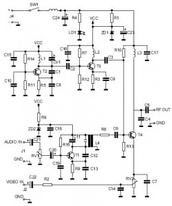
This is the circuit diagram of an audio/video modulator. The circuit converts audio and video signals into a UHF TV signal, allowing a video signal from a camera or other source to be connected to a standard TV set....
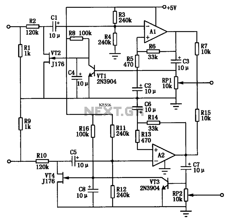
The Audio Automatic Gain Control (AGC) circuit monitors the output signal level of an audio preamplifier. When the input signal increases, the AGC circuit automatically reduces the amplifier's gain. Conversely, when the input signal decreases, the AGC circuit increases...
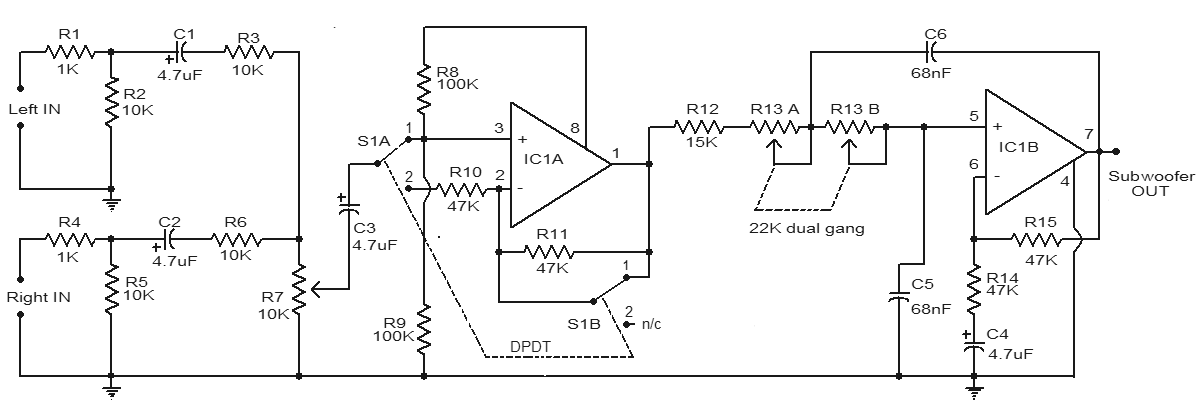
This is a simple subwoofer filter circuit that can be powered by a 12V DC source. It is particularly useful in automotive applications for subwoofers. The circuit functions as a low-pass filter, with a pass frequency adjustable between 60...
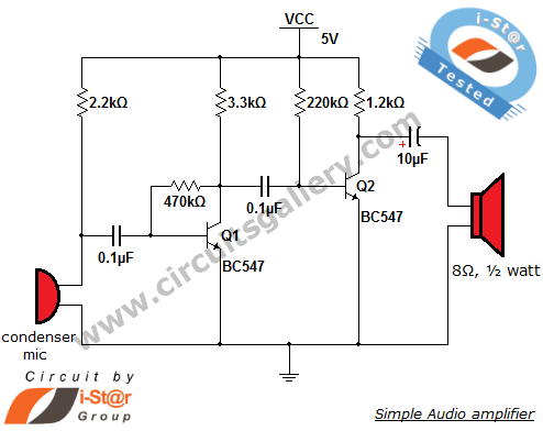
This circuit diagram is a simple and effective design for amplifying weak signals from a capacitive condenser microphone. It is suitable for sound sensing applications and various automatic robotic sensors. While a more complex audio amplifier circuit using the...
This circuit is very basic to build and puts out great power for your car or home. Keep all leads as short as possible. This circuit is designed to deliver substantial power output suitable for automotive or residential applications. The...