
photo sensor control relay

The circuit described utilizes a photodiode as a light sensor to control a normally open relay. The photodiode is typically a semiconductor device that operates based on the principle of light-induced electron-hole pair generation. In the absence of light, the photodiode is reverse-biased, which results in a high resistance state, allowing minimal leakage current to flow. This condition is critical for the operation of the relay, as it ensures that the circuit remains inactive until light is detected.
When light illuminates the photodiode, it generates electron-hole pairs, effectively reducing the resistance of the photodiode. This transition allows a small current to flow through the photodiode, but it is not sufficient to forward-bias transistor Q1. The transistor remains in its off state, preventing the relay from activating.
In contrast, when the ambient light level decreases, the photodiode's resistance increases significantly. This increase in resistance raises the voltage across the photodiode to a level that is adequate to forward-bias transistor Q1. As a result, transistor Q1 turns on, allowing current to flow through the relay coil, which activates the relay contacts. This action connects the load to the power supply, effectively turning it on.
Diode D2 is included in the circuit to protect transistor Q1 from voltage spikes that may occur when the relay coil is de-energized. These voltage transients, known as back EMF, can damage the transistor if not properly managed. The inclusion of D2 in parallel with the relay coil provides a safe path for the back EMF, allowing it to dissipate without affecting the transistor's operation.
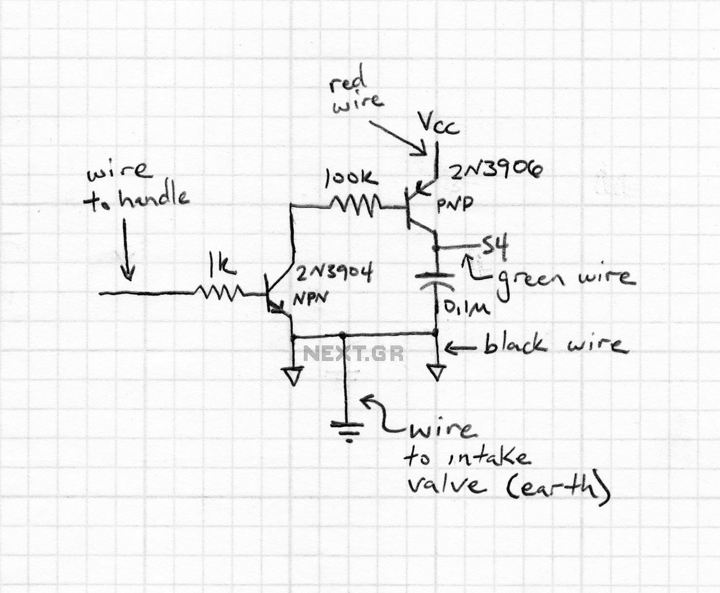
This photo-activated relay circuit provides a reliable means to control electrical loads based on light levels, making it suitable for applications such as automatic lighting systems, light-sensitive alarms, or remote control systems where manual intervention is minimized. The design ensures that the relay operates efficiently while protecting sensitive components from potential damage caused by switching transients.A photo or slightly activated relay normally open relay in the closed circuit / contact with the light. In this circuit, a photodiode is used to sense light. The photodiode has a high resistance in the absence of light strikes. The photodiode is connected to the reverse biased state. The only current flowing through it will be due to minority carr iers. When light falls on it, the minority current carriers in the wake of increasing the diode provides a low resistance. Because the voltage across the diode will not be sufficient to bias transistor Q1 and will be reset. Where there is darkness, the resistance increases photodiode and the voltage across it will be enough to move forward bias the transistor Q1 of the relay ON.
The diode D2 is used as a diode to protect transistor switching transients produced relay. In this way, the load on the relay contacts can be switched on and off using light strikes the photodiode. 🔗 External reference
Related Circuits

This lighting control unit will gradually decrease the brightness of one lamp while simultaneously increasing the brightness of another. The two loads maintain precise tracking without the need for manual adjustments. The gate of SCR1, a silicon-controlled rectifier, is...

An EEPROM is a type of non-volatile memory, which means it is used for permanently storing digital data without any power supply. EEPROM stands for Electrically Erasable Programmable Read-Only Memory. The advantage of this type of ROM is that...

The following circuit illustrates an Ultrasonic Sensor Circuit Diagram. This circuit is based on the MAX232 IC. Features include a quiescent current of 150mA. The Ultrasonic Sensor Circuit utilizes the MAX232 integrated circuit, which is primarily designed for converting signals...
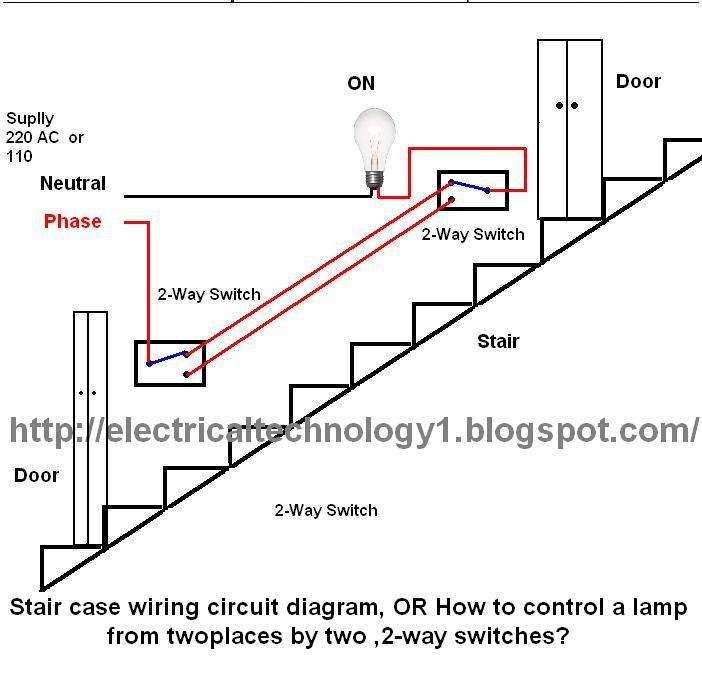
The circuit is complete, and the bulb is ON. To turn OFF the bulb from the upper switch at the top of the stairs, simply turn OFF the switch, which will break the circuit and turn the bulb OFF....
The finger, positioned within a light screen, is situated between a high-intensity LED emitter and a photocell. It generates a heartbeat signal that, when appropriately amplified, serves as the input for a PIC16F84 microcontroller. The microcontroller drives three common...

The circuit includes better channel separation, resulting in an increased stereo effect, as well as reduced noise and hum. This schematic will allow you to cancel or blend left and right channels of your stereo. Uses the LM4136 but...