
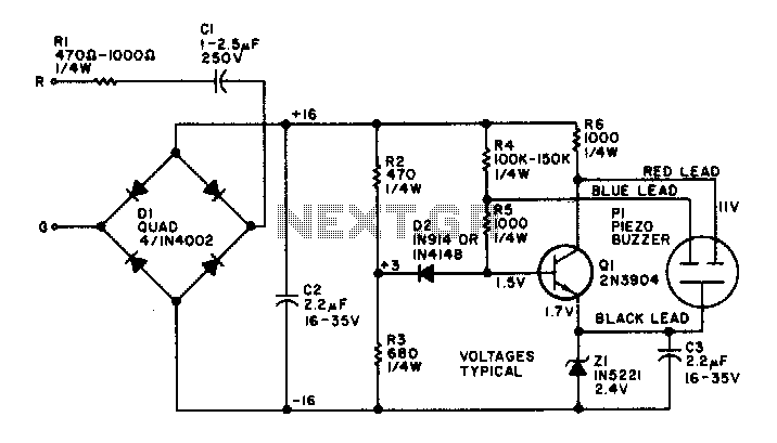
Piezoelectric buzzer

The quiz buzzer circuit functions as a simple and effective signaling device, commonly used in quiz competitions and games to indicate responses or correct answers. The primary component of this circuit is the piezoelectric buzzer, which converts electrical energy into sound.
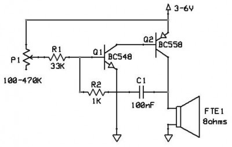
The circuit typically consists of a power supply, a switch (or multiple switches for multiple participants), a resistor, and the piezoelectric buzzer. When a participant presses the switch, it completes the circuit, allowing current to flow from the power supply through the resistor and into the buzzer. The resistor may be included to limit the current flowing to the buzzer, preventing damage and ensuring optimal sound output.
The piezoelectric buzzer operates by vibrating a piezoelectric material when an electric current is applied, producing sound waves. The frequency and volume of the sound can be influenced by the design of the circuit, including the values of the components used.
For enhanced functionality, additional features such as LED indicators can be integrated to provide visual feedback when the buzzer is activated. This can be particularly useful in noisy environments where audible signals might be less effective.
Overall, the quiz buzzer circuit is a straightforward yet versatile design that can be adapted for various applications, making it an essential component in interactive electronic projects.Hi guys. I`ve got a quiz buzzer circuit that is designed to output to a basic piezoelectric buzzer. What I really want to be able to do is to output.. 🔗 External reference
Related Circuits
A small circuit designed for various time measurement applications. It features an audible sound signal from the buzzer BZ1 and has the capability to drive an external circuit through the optocoupler IC2, once the appropriate circuit is connected to...
This circuit functions as an oscillator, capable of generating a sound wave or tone. The frequency of the tone, whether high or low, is adjustable via a variable resistor. The volume produced by this circuit is substantial; therefore, it...
The electronic bell operates without a power supply. Most resistors in the circuit are not critical, although capacitor C2 and resistors R2 and R3 perform optimally at the specified values. Omitting resistor R1 will increase the volume of the...
A piezoelectric sounder (self-drive type) consists solely of a piezoelectric diaphragm with a feedback electrode and is utilized in conjunction with an external drive circuit. The drive circuit for both types of sounders is a simple configuration comprising one...
In order to generate a single note you may try these simple circuits. With only three components you may implement some basic buzzers. You need a telephone earpiece for the first circuit. Any old telephone set has got one...
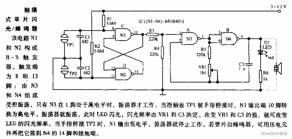
In the circuit, N1 and N2 form the RS flip-flop, with the trigger inputs located at pins 8 and 13. N3 and N4 create a controlled oscillator that operates only when pin 1 of N3 is high. When the...