
plc circuit diagram

The operation of PLC input and output cards is critical for ensuring reliable communication between the PLC and external devices. Input cards are designed to interface with sensors and input devices, receiving signals that may vary in voltage levels. The need for an external power supply arises because the input card itself does not generate the necessary voltage to power these devices. The ladder logic diagram serves as a visual representation of the connections and logic flow, facilitating easier understanding and troubleshooting during installation and maintenance.
In the input circuitry, the use of optocouplers plays a pivotal role. These components allow for the safe transfer of signals between different voltage domains while preventing high voltages from affecting the PLC's internal components. The design typically includes resistors to limit current and ensure that the optocoupler operates within its specified range. Additionally, protection diodes may be included to prevent damage from reverse polarity, ensuring that the circuit remains functional even in adverse conditions.
Output modules operate similarly, acting as interfaces between the PLC and external loads, such as motors or lights. These modules require an external power source to energize the connected devices. The conversion from the 5VDC logic level to higher voltage levels is achieved through the use of optocouplers or relays, which can handle the higher currents and voltages needed for the external circuits. The isolation provided by these components protects the PLC from potential damage caused by surges or faults in the external circuitry.
Overall, the integration of input and output cards within a PLC system is essential for creating a robust and flexible control environment. Proper circuit design, including the use of optocouplers and protective components, ensures that the system can operate safely and effectively across a variety of applications.PLC input cards rarely supply power, it means that needs external power supply for the inputs and sensors. Below is an Input card and Ladder Logic diagram that shows how to connect an AC input card. The PLC inputs must convert a variety of logic levels tothe 5VDC logic level used on the data bus. This can be done with circuits similar as the picture below. Basically the circuits condition the input to drive an optocoupler. This electrically isolates the external electrical circuitry from the internal circuitry. Other circuit components are used to guard against excess or reversed voltage polarity. As with the input modules, output modules rarely supply any power, but instead act as switch. External power supplies are connected to the output card and it will switch the power on or off for each output. PLC outputs must convert the 5VDC logic level on the PLC data bus to external voltage levels. The circuits will show on the picture below. Basically the circuits use an optocoupler to switch external circuitry. This electrically isolates the external electrical circuitry from the internal circuitry. Other circuit components are used to guard against excess or reversed voltage polarity. 🔗 External reference
Related Circuits
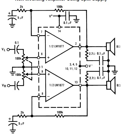
This audio amplifier circuit is designed to deliver 2W per channel continuously into 8-ohm loads. The LM1877 is engineered to function with a minimal number of external components while still offering flexibility for applications in stereo phonographs, tape recorders,...
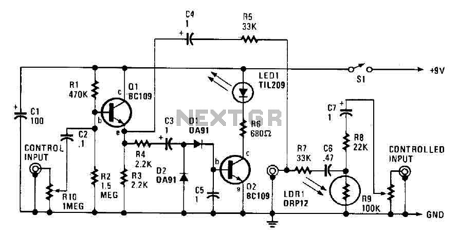
The automatic fader reduces the background music level when narration is in progress. The control input through RIO, a preset audio level control, is directed into an emitter-follower buffer stage (Q1). This buffer provides high input impedance and ensures...
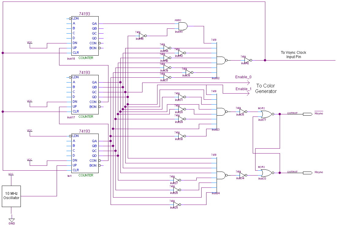
The complete schematic for this project is quite extensive. To view it, please click the image below. Due to its size, the explanation of the connections is divided into three sections: the Hsync Generator, Vsync Generator, and Color Generator....
A typical circuit for welding equipment is illustrated in the following circuit diagram. The turn-on delay can be accurately controlled with Potentiometer P2, allowing for effective discharge management. The welding equipment circuit typically incorporates several key components to ensure proper...
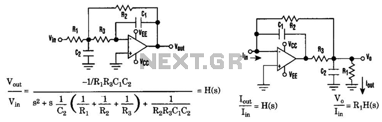
The low-pass Sallen-Key filter is a staple for designers because it contains few components. By redesigning the filter, a current-to-voltage conversion can be avoided when the input signal to be filtered is in current form. The Sallen-Key filter is a...
The two drawings utilize the LM324 operational amplifier to create a low-voltage comparator. Resistor R1 is part of a voltage divider circuit, while operational amplifier A1 is configured to a reference voltage level U1. Resistor R2 forms another voltage...