
Masochists Video Card Circuit

The schematic comprises several critical components that work in conjunction to generate synchronization signals and color outputs for a VGA interface. The Hsync Generator is crucial for generating horizontal synchronization signals, which are essential for displaying images on a monitor. The three 4-bit counters are configured to count clock cycles produced by the 10 MHz oscillator. As the counters increment, they reach specific thresholds that correspond to the timing requirements of the VGA standard.
The 7430 NAND gates play a pivotal role in determining the state of the Hsync signal. When the first counter reaches 210, the Hsync signal is activated, indicating the start of a new horizontal scan line. The subsequent value of 242 is crucial for resetting the signal, ensuring that the display timing remains accurate. The clear signal at 264 resets the counters, allowing for continuous operation without overflow or timing errors.
Hex inverters are strategically placed to maintain a stable logic level at the inputs of the NAND gates, ensuring that the logic conditions for triggering the Hsync signal are met. The use of AND gates is necessary for handling any values that exceed the 8-bit capacity of the 7430, thereby ensuring that the system can accommodate the full range of required values without losing synchronization.
Furthermore, the Color Generator is designed to manage the R/G/B signals effectively. The timing of these signals is critical; they must be enabled only during the appropriate segments of the VGA signal to prevent artifacts or incorrect colors from being displayed. The color enable signals ensure that the color data is only sent when the Hsync and Vsync signals indicate that it is valid to do so, maintaining the integrity of the visual output.
Overall, this schematic integrates various components to achieve a robust VGA signal generation system, ensuring precise timing and accurate color representation on the display.The full schematic for this project is really, really big so if you want to see it, go ahead and click the picture below. Since the schematic is so big I split the explanation of how things are connected together into three sections.
The Hsync Generator, Vsync Generator and Color Generator. The Hsync circuit uses 3x 4-bit counters to count up to specific values that trigger the Hsync signal as well as a clear signal to reset the counter value to 0. A 10 MHz crystal oscillator is input to the first 4-bit counter which counts up. The carry bit from the first counter is connected to the 2nd counter so that the 2nd counter will continue counting upward, likewise for the 3rd counter.
210 (0b11010010), 242 (0b11110010) and 264 (0b100001000) are the three unique values that the 7430 8-input NAND gates are looking for. 210 will trigger the Hsync signal to set to 1, 242 triggers it to reset to 0 and 264 is the clear signal which tells the counters to start counting from 0 again.
Some hex inverters are used to make sure the input into the 7430 NAND gate is "11111111" for each of the specific values we want to trigger Hsync and Clear at. AND gates are used whenever the value is larger than 8 bits, since the 7430 maxes out at 8-bits. Since the R/G/B color output cannot always be active, we need to make sure it is only enabled when the VGA timing allows for color signals to be active.
These two signals are fed into the color generator as color enable signals. 🔗 External reference
Related Circuits
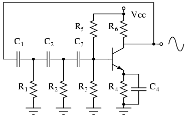
The phase shift oscillator produces a sine wave output in the audio frequency range. Resistive feedback from the collector results in negative feedback due to a 180-degree phase inversion from the base to the collector. The three 60-degree RC...
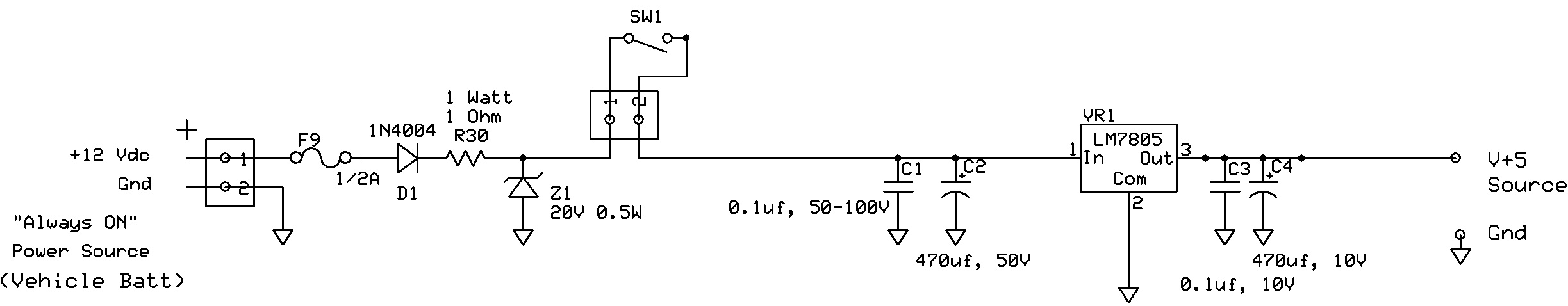
The circuit regulates approximately 12V from the car battery down to 5V for use by an Atmel AVR microcontroller. The presence of two capacitors on each side of the linear regulator LM7805 raises questions regarding their purpose. It is...
The circuit automatically lights a bulb upon the arrival of a telephone ring and simultaneously mutes the audio from the music system or TV while the telephone handset is off-hook. The lighting of the bulb not only indicates an...
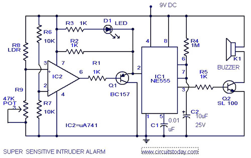
The circuit diagram represents an ultra-sensitive intruder alarm. A shadow from an intruder passing nearby is sufficient to trigger the alarm. The operational amplifier IC2 (uA 741) is configured as a sensitive comparator, with its set point determined by...
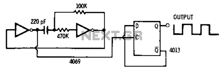
The 4013 pairs of D-type flip-flops in the astable multivibrator configuration are utilized as a binary divider output, generating an output frequency that is symmetrical, with a duty cycle of 50%. The 4013 integrated circuit contains two D-type flip-flops that...
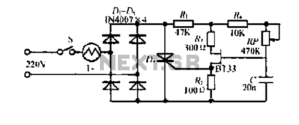
Electrical flow through the saddle j pounds. TV added in a controlled manner Qian Mountain amphipod species lI- ii mi pulsating chord electric. This electric again. The DC Bamboo Division I and the second voltage supply voltage step trigger...