
PLL FM demodulator 4046

The 4046 PLL is a versatile integrated circuit that can be configured for various applications, including FM demodulation. In this circuit, the device operates by locking onto the frequency of the input FM signal and extracting the modulating information contained within it. The PLL consists of two main components: a voltage-controlled oscillator (VCO) and a phase comparator.
The operation begins with the incoming FM signal being fed into the phase comparator. This comparator compares the phase of the incoming signal with the phase of the VCO output. When a phase difference is detected, the phase comparator generates an error voltage that adjusts the frequency of the VCO. This feedback loop continues until the VCO output frequency matches the frequency of the input signal, effectively locking onto it.
The output of the VCO is then filtered to obtain the demodulated baseband signal. This signal represents the original information that was encoded onto the carrier wave of the FM signal. Additional circuitry, such as low-pass filters, may be implemented to further refine the output and remove any high-frequency components that are not part of the original signal.
In practical applications, the 4046 PLL FM demodulation circuit can be used in various communication systems, including radio receivers and data transmission systems, where accurate demodulation of frequency-modulated signals is required. Proper design considerations, such as component selection and layout, are essential to ensure optimal performance and minimize noise and distortion in the demodulated output. Circuit is shown using the 4046 PLL FM demodulation circuit device comprising, IF FM demodulation circuit output by the input signal frequency signal.
Related Circuits
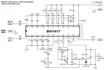
The circuit diagram of a stereo PLL FM transmitter based on the BH1417 chip is presented. This recent design from RHOM integrates numerous capabilities within a compact package. It features pre-emphasis and a limiter to maintain consistent audio levels...
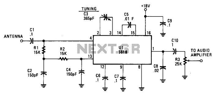
This simple AM circuit utilizes a 561B. It lacks an inductance/capacitance tuning circuit, as the 365 pF capacitor connected between pins 2 and 3 is responsible for all tuning. A good external antenna and a solid ground connection are...
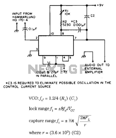
Useful for narrowband frequency modulation (NBFM) reception on older shortwave receivers that lack this capability, this circuit employs a phase-locked loop (PLL) integrated circuit, specifically the N565N. It was originally designed for use with an old Hammarlund HQ-170 receiver,...
The FM demodulator circuit, as illustrated in the figure, utilizes a 4046 Phase-Locked Loop (PLL) integrated circuit to convert the intermediate frequency FM input signal into a lower frequency output. The FM demodulator circuit based on the 4046 PLL IC...
This oscillator is known as the Colpitts oscillator and is voltage-controlled to facilitate frequency modulation (FM) and phase-locked loop (PLL) control. The transistor T1 should be a high-frequency (HF) transistor for optimal performance; however, in this instance, a common...
This demodulator is designed for the quadrature phase-shift keying (QPSK) modulator previously published by the same author in "Novel Low-Cost QPSK Modulator Needs No Adjustments" (Electronic Design, Sept. 16, 2002, p. 92). Utilizing common CMOS logic, it requires no...