
Polarity Gain Adjustment Circuit

The described circuit utilizes a quad operational amplifier configuration, which allows for versatile signal manipulation. The input buffer provided by the A section ensures that the input signal is isolated from the subsequent processing stages, preventing loading effects that could distort the signal. The fixed negative output of -4 V from op amp 0 serves as a reference point for the output variations, while the adjustable output from the other op amp allows for fine-tuning of the signal range.
The ability to vary the output from +2 V to +6 V peak enables a wide range of applications, particularly in audio and signal processing where phase and amplitude control are crucial. The D section's function of summing the outputs from the C and D sections facilitates the smooth transition of the output voltage, making it suitable for applications requiring precise control over the output signal's amplitude and phase.
In practical applications, this circuit can be employed in audio systems to create effects such as amplitude modulation or dynamic range compression, where the output signal needs to be carefully adjusted in relation to the input. Additionally, the capability to switch the phase of the output signal makes this circuit useful in applications such as phase-sensitive detection, where the relationship between input and output phases is critical for signal integrity and processing accuracy. Overall, this circuit exemplifies a flexible and effective approach to signal modulation using operational amplifiers. By adjusting one potentiometer, this circuit`s output can be varied from a positive-going version of the input signal, smoothly through zero output, then to a negative-going version of the input (see the figure). If the input signal is a positive pulse of, for example, +2-V peak/the output pulse amplitude can be smoothly varied from +2-V through ground (no output) to a -2-V peak.
Taking a closer look at the setup, assume that the signal has a +2-V peak input. The A section of the quad op amp is an input buffer, op amp 0 provides a fixed negative-going output of -4-V peak, and op amp supplies a positive-going output that varies from +2-V to +6-V peak. The D section adds the and C outputs. Thus, by varying the output, the circuit output varies smoothly from -2-V to +2-V peak. The circuit can, of course, also be used as a 07180 phase switcher. For instance, with a ground-centered sine-wave input of 4V p-p, the output varies from 4-V p-p in phase with the input, smoothly through 0 V, to 4V p-p 180 out of phase with the input.
Related Circuits
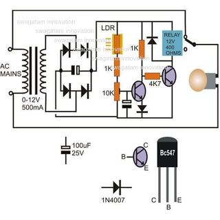
This circuit diagram illustrates a light-activated switch utilizing the National Semiconductor comparator IC LM311 and a light-dependent resistor (LDR). The configuration is based on a voltage comparator circuit centered around IC1. The non-inverting input of IC1 receives a reference...
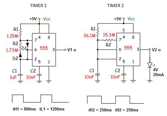
Unfortunately, there is no breadboard available for testing; however, modifications can be made to the PCB. The 1K potentiometer has been removed until the strobe functionality can be established. The circuit in question appears to involve a strobe light mechanism,...
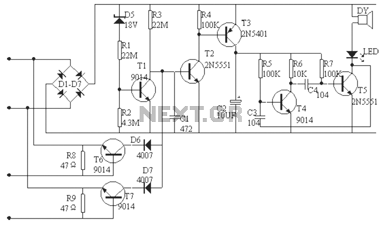
The phone alarm device is designed to monitor and prevent unauthorized use of a telephone line. When interference signals are detected on the line due to theft attempts, the alarm activates, preventing the thief from making calls while alerting...
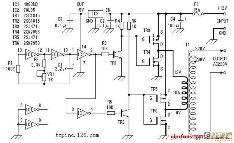
The inverter described in this text utilizes a MOS field-effect transistor and a standard power transformer. Its output power is determined by the capabilities of both the MOS field-effect transistor and the transformer, eliminating the need for complex voltage...
The circuit includes a comprehensive array of components such as vibration sensors, a follower, a lamp relay control circuit, a voice sounding circuit, a high-frequency oscillation circuit, and an AC rectifier buck power supply circuit. The vibration sensor is...
SPI Integrated Circuit Bus, IC Buses, an IC, Chip-to-Chip Bus Serial Peripheral Interface, Integrated Circuit Bus types, and IC Bus Electrical Interface Descriptions. Peripheral Interface (SPI) circuit is a. The Serial Peripheral Interface (SPI) is a synchronous serial communication...