
Polarity Protection Circuit

A series diode is an effective method for preventing reverse polarity in electronic circuits. When a power supply is connected with the correct polarity, the diode allows current to flow through the circuit. However, if the power supply is connected in reverse, the diode becomes reverse-biased and blocks the current, thereby protecting sensitive components from damage.
In a typical implementation, a silicon diode, such as a 1N4001, is placed in series with the positive line of the power input. The anode of the diode is connected to the power source, while the cathode is connected to the load. This configuration ensures that under normal operating conditions, the diode conducts and the load receives the necessary voltage.
For applications requiring higher efficiency, Schottky diodes can be utilized due to their lower forward voltage drop compared to standard silicon diodes. This characteristic results in reduced power loss and improved overall efficiency of the circuit.
It is important to consider the current rating and reverse voltage rating of the diode to ensure it can handle the expected load and prevent breakdown during reverse polarity conditions. Additionally, the thermal management of the diode should be assessed, especially in high-current applications, to prevent overheating and potential failure.
In summary, the series diode configuration is a straightforward and reliable method for polarity protection in electronic circuits, safeguarding components from reverse voltage damage while maintaining operational integrity under normal conditions.The most simple polarity protection tehnique is to connect a series diode to the power line input. The diode conducts only when the power supply protection.. 🔗 External reference
Related Circuits
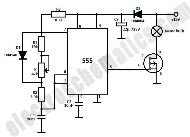
This light dimmer is designed to adjust the brightness of 12V light bulbs utilizing the widely recognized 555 timer, which is configured as an astable multivibrator. The pulses generated by the timer control the power delivered to the light...
This ultra wide range timer utilizes a 555 timer as its core component, along with two 4017 decade counters and a 4020 binary counter that function as frequency dividers, which can be selectively switched in and out. Additionally, the...
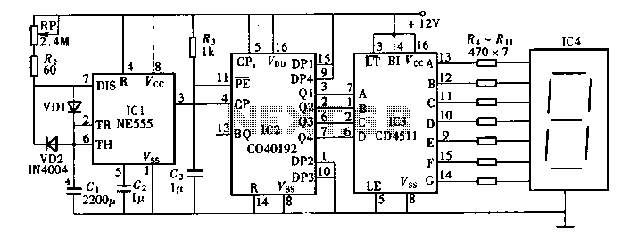
Digital timers feature a clear and precise display. They represent time intervals based on pulse signals, which are decoded by a digital device with a digital display unit. The circuit described pertains to a digital display for these timers,...
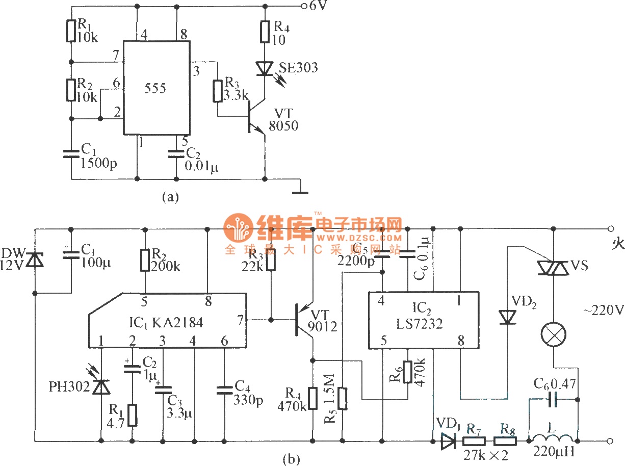
This is an infrared emission circuit diagram. The NE555 circuit generates a 40 kHz pulse, which is sent by the infrared emission control SE303 after being amplified by VT. The remote receiver and infrared dimming circuit are composed of...
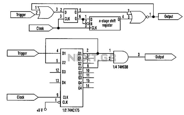
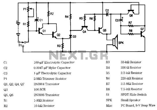
This approach utilizes a Hip-Hop, a shift register, and two gates (A). Before the one-shot pulse, the output of the NOR gate is 0. Consequently, the data input of the D-type flip-flop is equivalent to the trigger. When a...
A 12-volt power supply is used to operate a sequencer board that controls external relays for coaxial relays, a preamplifier, and an amplifier. The sequencer board features DIL relays designed to drive these external relays. Although there are more...