
Dim Light Bulbs with 555 IC Circuit

The circuit operates by generating a series of pulse-width modulated (PWM) signals through the 555 timer in its astable mode. In this configuration, the timer continuously switches between its high and low states, producing pulses at a frequency determined by external resistors and capacitors connected to the timer. The duty cycle of these pulses can be adjusted by varying the resistance or capacitance, which in turn modifies the average voltage supplied to the light bulb.
The output from the 555 timer is connected to a power transistor, which acts as a switch to control the current flow to the light bulb. When the 555 timer outputs a high signal, the transistor is turned on, allowing current to pass through the light bulb. Conversely, when the output is low, the transistor is turned off, cutting the current. By adjusting the duty cycle of the PWM signal, the effective brightness of the light bulb can be increased or decreased, providing a smooth dimming effect.
To ensure stability and prevent flickering, it is important to choose appropriate values for the timing components. Additionally, the circuit may include a smoothing capacitor at the output to further reduce any ripple in the power supply to the light bulb, enhancing the dimming performance. The design can be implemented on a printed circuit board (PCB) for better reliability and compactness. Proper heat sinking may also be necessary for the power transistor to prevent overheating during prolonged operation.This light dimmer is used to dim the intensity of 12V light bulbs using the well-known 555 timer that is configured as an astable multivibrator. The pulses.. 🔗 External reference
Related Circuits
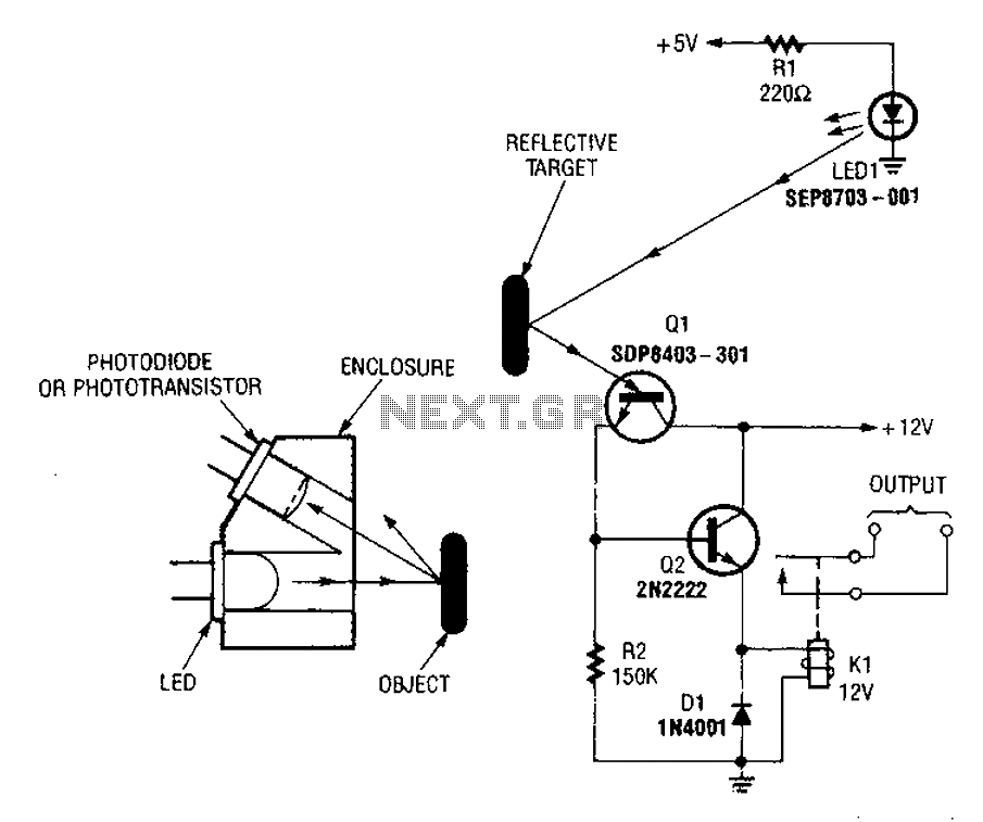
A reflex isolator detects the presence of an object by reflecting light from the object back to the sensor. This technique is effective when an object is in close proximity to the sensor. Reflex isolators, also known as proximity sensors,...
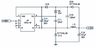
The following file is an application note describing the two stages of an electronic ballast for a 250 W HID metal halide lamp. The components include. The application note outlines a two-stage electronic ballast designed specifically for a 250 W...
Incorporate resistors in a parallel configuration to enhance audio input. To control the volume for each input channel, integrate a linear trimmer or potentiometer with the following configuration: pin 1 connects to ground, pin 2 serves as the output,...
This project involves a straightforward soil moisture detection circuit that utilizes only four components and operates with a 3-volt battery. The circuit is designed to identify the presence of moisture in the soil of any plant and activate an...
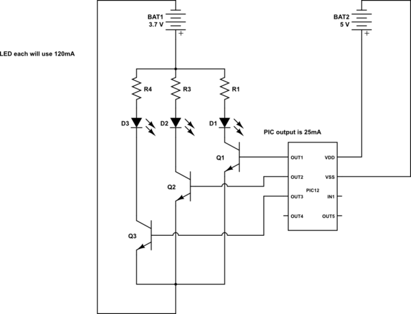
This is a conceptual schema utilizing a PIC12 microcontroller to control the blinking of three LEDs, each exhibiting different blinking patterns. There are several questions that need to be addressed. The circuit design involves a PIC12 microcontroller, which is a...

Designing an audio amplifier from scratch using discrete components is an engaging task, as it enables users to create amplifiers that meet diverse requirements. Audio amplifiers can enhance low-level sounds from mobile devices, making them louder and more vibrant....