
Positive And Negative Voltage Power Supply

This circuit design utilizes a Burr-Brown INA105 difference amplifier, which is known for its high precision and low offset voltage characteristics, making it suitable for applications requiring accurate voltage references. The choice of a potentiometer for gain control provides a user-friendly method for adjusting the output voltage range seamlessly. The configuration allows users to fine-tune the output voltage between the specified limits while maintaining a high degree of accuracy.
The inverting amplifier configuration with a gain of -1.0 V/V ensures that the output voltage is an inverted version of the input voltage, which is particularly useful in applications where signal inversion is necessary. The precision of the circuit is enhanced by the INA105's low noise and high common-mode rejection ratio (CMRR), which minimizes the impact of external noise on the output voltage.
In practical applications, the circuit can be employed in laboratory settings, test equipment, or any scenario where a stable and adjustable voltage reference is required. The ability to achieve exactly 0 V without offset is particularly advantageous in calibration tasks or when interfacing with sensitive electronic components that require precise voltage levels.
Overall, this precision voltage source circuit exemplifies effective design principles in analog electronics, combining high-performance components with user-adjustable features to meet the demands of various electronic applications. This circuit provides a precision voltage source that can be adjusted through zero to positive a nd negative voltages, which eliminates reversing connections on the power supply. Also, it is possible to get exactly 0 V, without some offset. As to how this circuit works, first consider the -1 V/V to +1 V/V linear gain-control amp (see the figure). A Burr-Brown INA105 difference amp is used in a unity-gain inverting amp configuration. A potentiometer is connected between the input and ground. The pot"s slider is connected to the noninverting input of the unity-gain amp; this input is typically connected to ground.
With the slider at the bottom of the pot, the circuit is a normal-precision unity-gain inverting amp with a gain of -1.0 V/V ± 0.01% maximum. With the slider at the top of the pot, the circuit is a normal-precision voltage follower with a gain of ± 1.0 V/V ± 0.001% maximum.
With the slider in the center, there"s equal positive and negative gain for a net gain of 0 V/V. The accuracy between the top and the bottom will usually be limited by the accuracy of the pot.
Related Circuits
This circuit clearly indicates the supply voltage level in a larger device. When the indicator receives a stable 12 volts, LED1 emits a steady yellow light. If the input voltage drops below 11 volts, LED1 begins to blink, with...
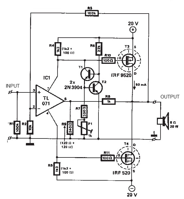
The audio amplifier illustrated in this circuit diagram is a straightforward and efficient audio amplifier circuit based on the TDA1308 integrated class-AB stereo headphone amplifier. This device is manufactured using a 1 mm Complementary Metal Oxide Semiconductor (CMOS) process...
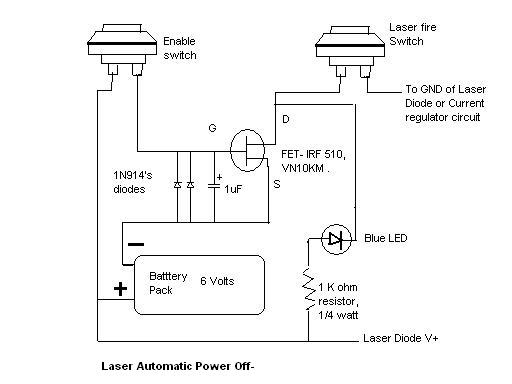
Here is the automatic laser power-off circuit schematic. This circuit features a visible power indication. In this case, the ground is connected on one side. The automatic laser power-off circuit is designed to enhance safety and efficiency in laser applications...

The hobby circuit described utilizes a unique approach to generate approximately 12,000 volts with a current of about 5 µA. It employs two silicon-controlled rectifiers (SCRs) that form dual pulse generator circuits. These SCRs discharge a 0.047 µF capacitor...
The purpose of this report is to provide background and findings of our senior project. We will discuss four steps that we used to complete our final project. The four steps of our project were research and development, design,...
The first schematic is designed for individuals who exclusively purchase electronic components from Radio Shack. It allows for a straightforward shopping experience, enabling one to acquire all necessary parts in-store. For the heat sink, it is recommended to visit...