
Potentiometer-Position V/F Converter

The AD652 IC is designed to convert an analog voltage signal into a corresponding frequency signal. In this specific application, the potentiometer serves as a variable resistor, allowing for the adjustment of the input voltage from 0 to 5 V. As the position of the potentiometer is altered, the voltage output changes proportionally, which the AD652 interprets to generate a frequency output that ranges from 0 Hz to 100 kHz.
The circuit typically consists of the AD652 connected to the potentiometer, with the output frequency being measured or utilized in further electronic components or systems. The configuration may include additional passive components such as resistors and capacitors to stabilize the circuit and filter any noise that may affect the accuracy of the frequency output.
To ensure proper functionality, the power supply for the AD652 must be within the recommended voltage range, and the reference voltage should be stable to maintain accuracy in the conversion process. The output frequency can be monitored using a frequency counter or fed into a microcontroller for further processing, enabling applications in various fields such as robotics, automation, and measurement systems where precise position sensing is required.
Overall, the synchronized V/F converter utilizing the AD652 offers a reliable solution for translating analog voltage signals into frequency outputs, making it suitable for a wide range of applications where positional feedback is necessary. In this application, an AD652IC is used in a synchronized V/F converter that derives its input from th e position of a potentiometer. This can represent a position of a mechanical component, weight, size, etc., to give a 0-to-100-kHz output versus the O-to-5-V output from the potentiometer.
Related Circuits
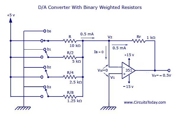
A digital-to-analog (D/A) converter utilizing binary-weighted resistors is illustrated in the accompanying figure. In this circuit, the operational amplifier (op-amp) is configured in inverting mode, although it may also be arranged in non-inverting mode. The schematic represents a 4-bit...
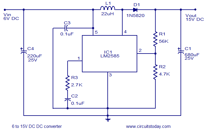
A simple and efficient 6 to 15V boost/step-up DC to DC converter based on IC L2585. This voltage converter circuit requires few external components. The circuit utilizes the L2585 integrated circuit, which is designed for high-efficiency voltage boosting applications. The...
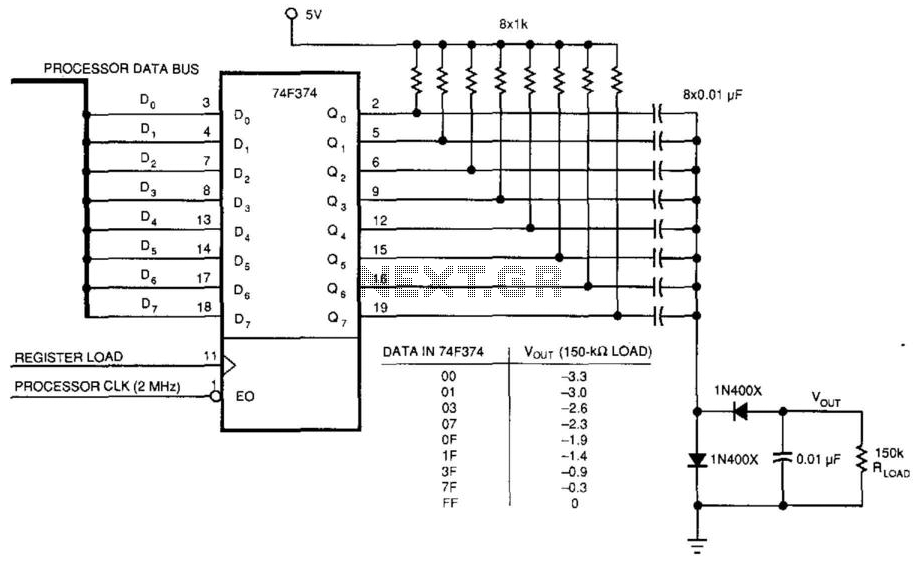
This circuit was used to produce a variable negative voltage for contrast control of an LCD display. A 74F374 generates a square wave that is AC coupled to a rectifier and load. By using the microprocessor clock and data...
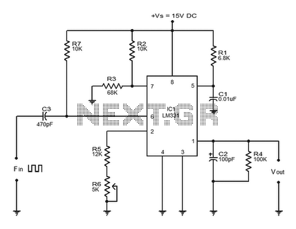
The LM331 is a precision voltage-to-frequency converter developed by National Semiconductors. This integrated circuit (IC) has various applications, including analog-to-digital conversion, long-term integration, voltage-to-frequency conversion, and frequency-to-voltage conversion. Its wide dynamic range and excellent linearity make it suitable for...
This inverter circuit can provide up to 800mA of 12V power from a 6V supply. For example, you could run 12V car accessories in a 6V car. The circuit is simple, about 75% efficient and quite useful. By changing...
The operation of the converter relies on the weighted addition and transfer of the analog input levels to the digital output levels. It comprises comparators and resistors. Although, theoretically, the number of bits is unlimited, each bit requires a...