
Power amplifier 2X5W with TDA1516Q circuit

This stereo amplifier circuit is designed to provide effective amplification with a minimalistic approach, making it suitable for various audio applications. The core component of this amplifier is a single operational amplifier (op-amp), which simplifies the design by reducing the number of external components required.
The op-amp is configured in a non-inverting amplifier configuration, which allows for high input impedance and low output impedance, ideal for driving speakers. The gain of the amplifier can be set using feedback resistors, ensuring that the output power meets the specified requirement of 2x5W into a 4-ohm load.
To achieve the stated output power, the power supply voltage must be appropriately chosen, typically in the range of ±12V to ±15V, depending on the specific op-amp used. The output stage of the amplifier may include additional components such as capacitors for coupling and bypassing to ensure stable operation and minimize distortion.
With a total harmonic distortion (THD) of 0.5%, the amplifier maintains a good balance between performance and simplicity. This makes it an excellent choice for applications where space and component count are critical, such as in portable audio devices or compact audio systems.
In summary, this simple stereo amplifier design leverages the capabilities of a single op-amp to deliver substantial audio power while keeping the circuit straightforward, making it accessible for both beginners and experienced electronics enthusiasts.A simple STEREO amplifier, with minimal external components. It use one only opamp., that is capable to give output power 2X5W in the 4 ohms, with distortion 0.5%.. 🔗 External reference
Related Circuits
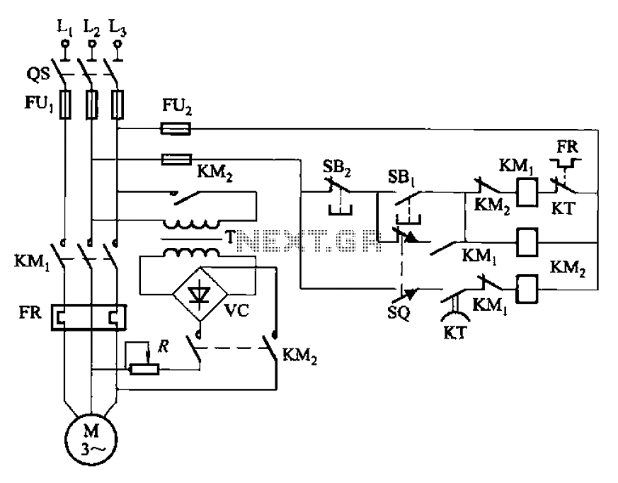
The circuit illustrated in Figure 3-136 incorporates a limit switch (SQ) that, when the motor operates a mechanical device to reach a predetermined position, cuts off the power and initiates dynamic braking for fast and accurate positioning. This configuration...
This circuit utilizes a standard loudspeaker, enabling it to function as a microphone. It allows for the use of an inexpensive loudspeaker in this capacity. Sound waves impacting the speaker cone result in variations in the voice coil. The...
Drying the motor winding circuit current imbalance. Below is a circuit diagram of the motor winding current imbalance drying. The circuit for drying motor winding current imbalance is designed to address the issue of uneven current distribution across the windings...

The proposed remote control circuit can be utilized to control any electrical device within a range of 100 meters. This concept involves modifying an existing remote bell unit circuit, making the process straightforward. However, the construction aspect necessitates electronic...
This easy electronic buzzer circuit is built based on a timer that operates to generate frequency. The IC timer NE555 is used as an astable multivibrator operating at approximately 1 kHz, producing a sound when powered on. The sound...
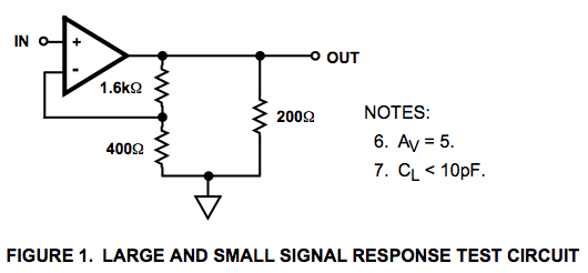
Here is a circuit diagram for a signal response test circuit from the specification sheet for a HA-5195 operational amplifier. It appears to be a non-inverting amplifier circuit with a gain of 5, along with a 200-ohm resistor connecting...