
Power Control

The circuit described offers a versatile solution for controlling AC loads with a focus on safety and functionality. The integration of a two-transistor flasher circuit enhances the reliability of triggering mechanisms while minimizing the effects of line voltage variations. The design's adaptability allows for various control methods, making it suitable for numerous applications ranging from lighting to motor control.
Safety considerations are paramount, given the potential hazards associated with high voltage AC circuits. It is essential for individuals constructing or modifying this circuit to possess the necessary expertise and knowledge to handle line voltage safely. The use of protective devices such as GFI breakers and fuses is strongly recommended to mitigate risks.
The circuit's RF noise generation is another critical factor, necessitating the implementation of effective filtering solutions to prevent interference with nearby electronic devices. The choice of components, such as rectifiers and transistors, should be carefully considered to ensure compatibility and performance within the desired specifications.
Overall, this circuit design exemplifies a practical approach to electronic control of AC loads, merging functionality with safety and adaptability.The circuit below is similar to designs using unijunction transistors to generate the triggering pulse. The unijunction is replaced by a two-transistor "flasher" circuit that drives a pulse transformer. This type of circuit gives a wide range of control while exhibiting little hysteresis or line voltage sensitivity.
The two diodes rectify the line voltage such that the flasher sees a positive voltage pulse on each half-cycle and, after a delay set by R and the 0. 1uF capacitor, the flasher circuit triggers the triac. The capacitor discharge is deep so the dimmer starts fresh on the next half-cycle. Note that the triac always gets the same polarity of trigger pulse. The dimmer may be controlled in a number of ways. The first option for R shows a typical mechanical control and the second option shows the use of an opto-isolator for electrically controlling the dimmer. The electronic control would be useful in applications like computer control, color organs, power flashers, heaters, speed controllers, and other feedback systems.
The base of the PNP is another sensitive spot to add control but the designer must remember that the whole circuit must be floating and large voltage swings are present. Remember, the entire circuit is "hot" and dangerous! Line power circuitry should be constructed only by qualified persons. GFI breakers are always a good idea! The flasher could be powered from a full-wave rectified transformer secondary if line isolation is desired.
Do not filter the rectified voltage or the circuit will not work properly. Use a fairly high voltage secondary, perhaps 50 VRMS to get full power control. (Lower if using a 2N4401. ) The circuit will generate significant RF noise and a line filter is recommended. (It is usually pretty easy to find potted line filters in surplus catalogs. ) Also, make sure to include a fuse, as indicated. The circuit may be used for other AC applications including motor speed control and the clever designer might add in positive feedback based on current consumption to achieve near constant motor RPM with changing load (a non-trivial challenge). Or, consider applying negative feedback via the optoisolator. The 1N4003 only see about 100 volts reverse and the current is fairly low so other rectifiers may be substituted.
The 2N5551 may be replaced with a lower voltage transistor like the 2N4401 if the 10k resistor is decreased to 6. 8k (to limit the collector voltage). Full brightness will be reduced a slight amount but for most applications the loss will be insignificant.
The 27k resistors should be at least 1/2 watt or the resourceful experimenter may wish to double their value along with the 10k if the triac is sufficiently sensitive. The pulse transformer was designed for triggering thyristors but other types may work as substitutes - try a 1:1 phone transformer, for example.
Here is a hand-made dimmer built onto a piece of laminate. The triac is an RCA T2710 and the pulse transformer is a Sprague 1:1, 66Z906. (Both are older parts from my vast surplus collection!) Read the construction page for more information about this project. Users of ExpressPCB may download the design file. The board was built into a grounded metal chassis with a line filter and fuse. I like the idea of LED light strings that rarely need new bulbs but the flicker drives me crazy! Here`s the solution for single strings of LEDs all in series: Most strings will run well on about 20 mA of DC instead of the AC which makes them flicker and this simple circuit converts the AC to DC and reduces the voltage a bit.
The 39 uF capacitor should have a 200 volt or higher rating but the capacitance may be a bit less, perhaps as low as 10 uF. The rectifier diode may be 🔗 External reference
Related Circuits
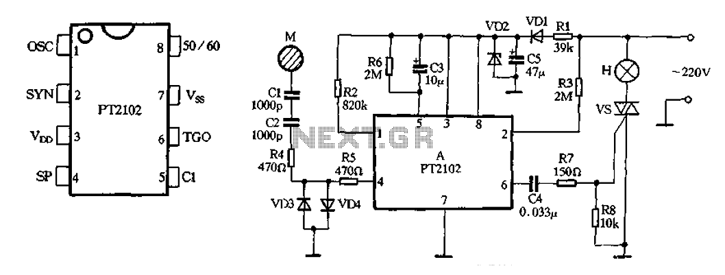
A 220V AC input is stepped down using a resistor (Rl) and then rectified by a diode (VDI), followed by filtering through a capacitor (C5) to produce an output voltage of approximately 9V DC for a manifold power supply....
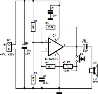
A powerful buzzer in the room, combined with a pushbutton at the bottom of the stairs or in the kitchen, could be very useful in such situations. The core of this circuit is formed by IC1, a TDA2030. This...
If an application utilizes a MOSFET to switch a load, it is straightforward to incorporate short-circuit or overload protection. This can be achieved by leveraging the internal resistance RDS(ON), which generates a voltage drop proportional to the current flowing...
This circuit is a modified version of a function-generator circuit. It features a battery-powered sine wave generator that can be continuously adjusted from 100 Hz to 10 kHz. The described circuit utilizes a sine wave generator to produce a continuous...
The ADM1066 from ADI Company is a monitoring device designed to manage various configurable sequencing applications. It features 12 ADCs and 6 8-bit DACs with a voltage output precision exceeding 0.5% at 25 degrees Celsius. This device is primarily...
The circuit safely delivers approximately 20 Amps at 13.8V. For lower current applications, a separate current limiting output capable of 15mA up to a total of 20A has been included. The power transformer should be able to supply at...