
Power frequency noise filter PC822 schematic
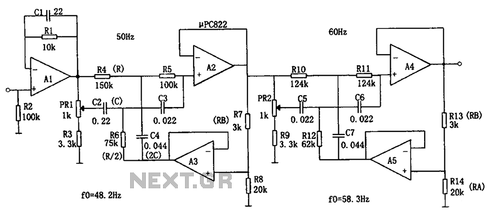
The double-T filter circuit is an effective solution for reducing power supply noise in electronic systems, particularly in applications where precision is critical, such as sensor signal processing. The design utilizes operational amplifiers to improve the Q factor, thus enhancing the selectivity of the filter. The ability to adjust the resonant frequency using potentiometers allows for fine-tuning based on the specific frequency of the noise present in the power supply.
In practical applications, the circuit can be integrated into various electronic devices to mitigate interference from the 50Hz or 60Hz power lines. The design's reliance on both resistive and capacitive components ensures that it can effectively handle a range of frequencies, while the feedback mechanism permits dynamic adjustments to the filter characteristics based on the operating environment.
When implementing this filter, consideration should be given to the layout and component selection to minimize parasitic capacitance and inductance, which could adversely affect performance. Additionally, the choice of operational amplifiers should align with the desired frequency response and gain characteristics to achieve optimal filtering results. Overall, this circuit serves as a robust solution for enhancing signal integrity in the presence of power supply noise. As shown in FIG frequency power supply noise filter circuit. The circuit is a double-T filter, can be used to amplify (such as sensors) weak signal, to mixed 50Hz (or 60Hz) pow er supply frequency noise will be filtered out. If using only the RC element composed of such filter, the Q value is generally low, and the attenuation characteristic having broadband characteristics. Using op amps and add positive feedback can improve the Q value. Let Q value at this time is Q, then Q Q/(1 a K), where, K RA/(RA + RB). Changing the coefficient K can make Q value increases. The resonant frequency of the circuit is fo 1/2 RC, positive feedback element of R/2 and 2C. Taking into account the characteristics of using a capacitive decentralization, the resonant frequency to be set lower, then the potentiometer PR1 and PR2 to adjust the frequency to 50Hz (or 60Hz).
When adjusting the input 50Hz (or 60Hz) sinusoidal voltage, filter it through PR adjust the output voltage to a minimum. With this filter, if the input power supply noise is not a sine wave, there will be a high-frequency component by the filter.
AC power is generally higher harmonics 3,5,7 and other odd harmonics can be filtered by low-pass filter access to these harmonics.
Related Circuits
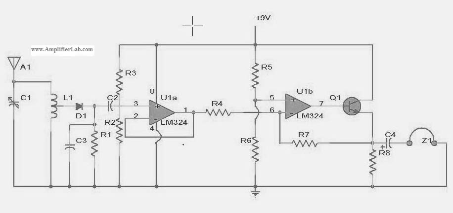
The following circuit illustrates a power amplifier electronic circuit, specifically a tube audio RF amplifier circuit diagram. This circuit is based on the LM324 integrated circuit. The power amplifier circuit utilizing the LM324 operational amplifier is designed to enhance audio...
The losses in a bridge rectifier can become significant when rectifying low voltages. The voltage drop across the bridge is approximately 1.5 V, which constitutes about 25% loss with an input voltage of 6V. This loss can be reduced...
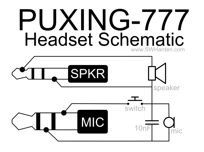
A speaker, microphone, and transmit button circuit designed for the Puxing 777 radio, which is likely compatible with all Puxing radios. The circuit was reverse-engineered from an earphone/microphone headset that originally accompanied the radio to understand its functionality. The...
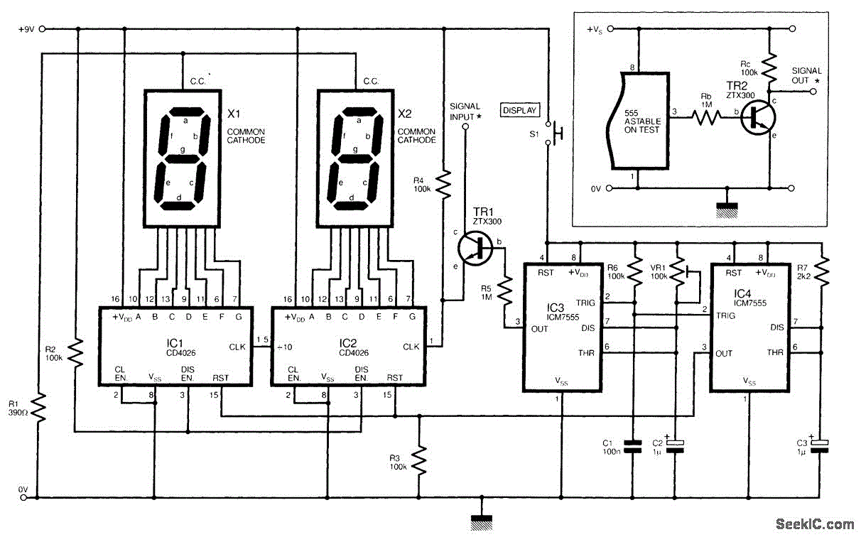
The circuit illustrated is a straightforward digital frequency meter that displays the frequency in hertz of an astable 555 timer. It may potentially be modified for alternative applications. An NPN transistor, TR2, is linked to the 555 astable timer...
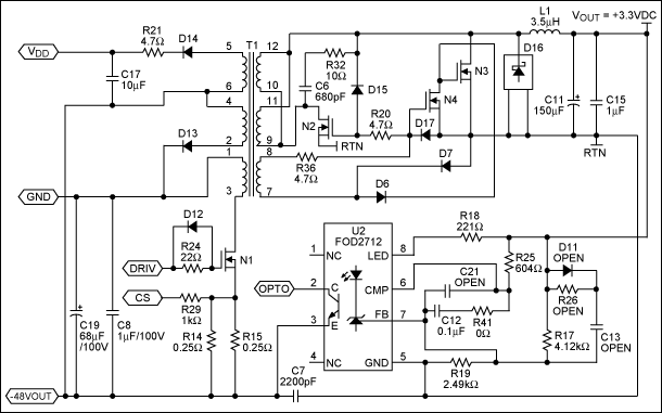
A PoE Plus power level of 30 W can be achieved by utilizing an external MOSFET along with a controller that is compatible with the older standard. Power over Ethernet (PoE) technology enables the delivery of electrical power along with...
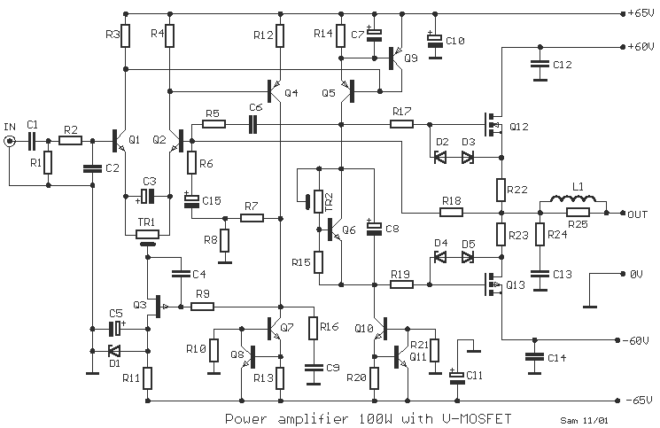
One still designing that it uses in the exit transistor of technology V-mosfet. This transistors to us offer a lot of virtues concerning the simple bipolar transistors, as high speeds, thermic stability, low distortion etc. Beyond this circuit use...