
Low voltage regulators

The described circuit employs a series of components to regulate voltage effectively while ensuring protection against potential faults. The primary elements include power transistors, zener diodes, resistors, and a heatsink for thermal management. The configuration allows for dual functionality, accommodating both positive and negative ground systems, which is critical for versatility in automotive applications.
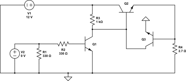
The voltage regulation is achieved through the use of a zener diode, which sets the reference voltage for the circuit. Resistor R1 is selected based on the desired zener voltage, ensuring that the output remains stable at either 6, 7, or 9 V, depending on the specific application requirements. The current flowing through the circuit is monitored, and under normal conditions, the voltage across R2 is maintained below the threshold that would trigger the activation of Q2.
In scenarios where the load demands exceed the circuit's capacity, Q2 acts as a protective switch. When the voltage across R2 rises above 500 mV, indicating an overload condition, Q2 conducts, effectively shutting off Q1. This mechanism protects the regulating transistor from damage due to excessive current, ensuring the longevity and reliability of the circuit.
Furthermore, the design's integration of power transistors directly onto the heatsink without insulating spacers not only simplifies assembly but also improves thermal dissipation. This feature is particularly advantageous in automotive environments where component temperatures can fluctuate significantly. Overall, the circuit exemplifies a robust solution for voltage regulation in automotive applications, combining efficiency, safety, and adaptability.These short-circuit protected regulators give 6, 7, and 9 V from an automobile battery supply of 13 V nominal; however, they will function just as well if connected to a smoothed dc output from a transformer/rectifier circuit. Two types are shown for both positive and negative ground systems. The power transistors can be mounted on the heatsink without a mica insulating spacer thus allowing for greater cooling efficiency.
Both circuits are protected against overload or short-circuits. The current cannot exceed 330 mA Under normal operating conditions the voltage across R2 does not rise above the 500 mV necessary to turn Q2 on and the circuit behaves as if there was only Q1 present. If excessive current is drawn, Q2 turns on and cuts off Ql, protecting the regulating transistor. The table gives the values of Rl for different zener voltages.
Related Circuits
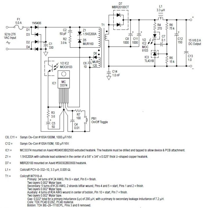
This switching power supply circuit diagram is based on the MC33374 high-power voltage switching regulator IC manufactured by Motorola Semiconductor. The MC33374 switching power supply circuit will provide a maximum output power of around 90 W and requires few...
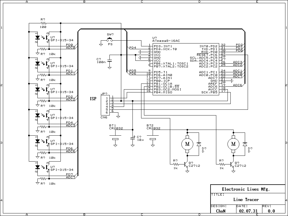
Recently many kind of robot contests have being opened and some interesting reports of the challenge are found on the web. The Line Following is a kind of the robot contests to vie running speed on the line. I...
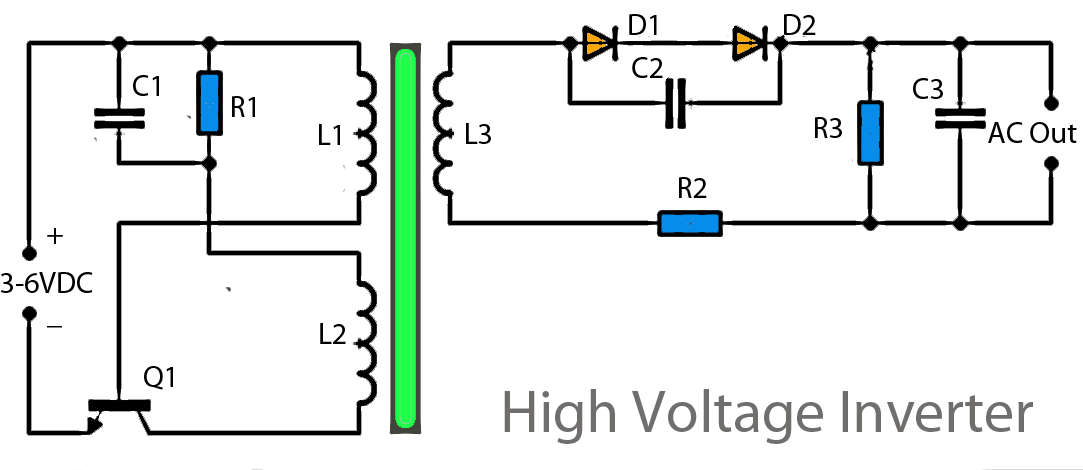
This inverter circuit operates using a transistor and transformer, along with other components, to elevate the voltage. The input supply voltage ranges from 3V to 6V DC, which is then converted to a high voltage AC output. However, the...
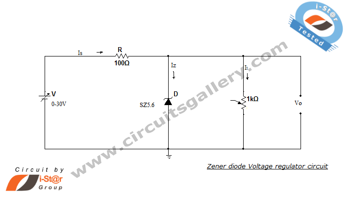
A Zener diode regulator is a fundamental electronic circuit valuable for hobbyists. This circuit provides a regulated output voltage, suitable for biasing other circuit components. The Zener diode operates in the reverse breakdown region, maintaining a nearly constant voltage...
This simple and inexpensive circuit can produce a dual (positive and negative) voltage from a single supply input. It is therefore extremely useful for powering opamp and other circuits that require a dual voltage from a single battery. The...
The second transistor (T2) is activated by the current passing through the resistor (R1). When a DALI slave unit is connected, this current matches the current flowing through the power transistor (T1). The resistor's value is selected so that...