
Charger circuit V
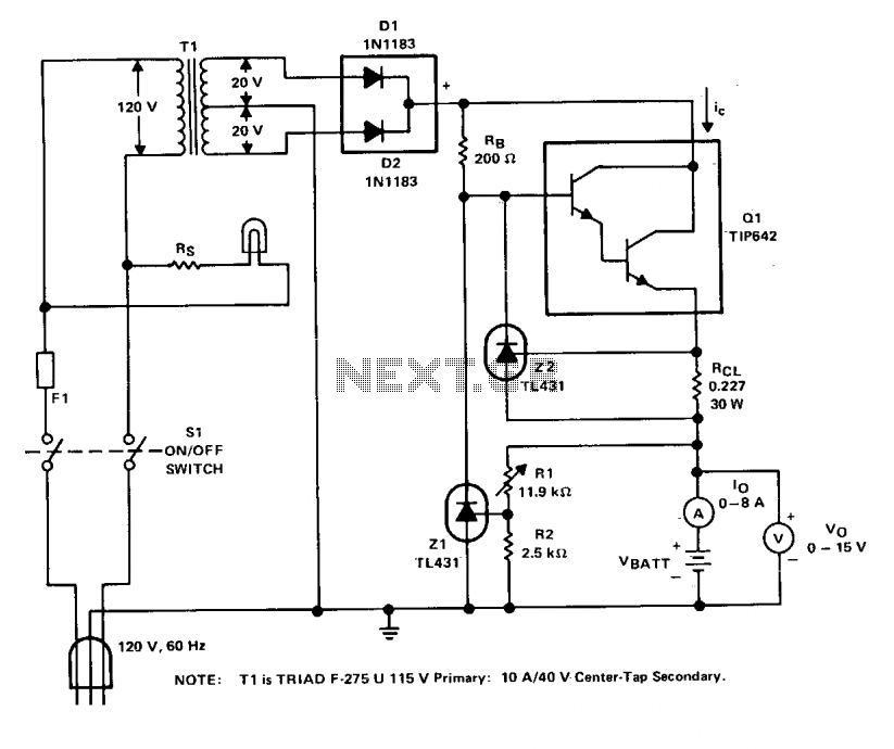
The charger circuit is designed to efficiently manage the charging process of lead-acid batteries while ensuring the safety and longevity of both the charger and the battery. The charging voltage of 14.4 V is specifically chosen to optimize the charging process for six series-connected cells, each rated at 2.4 V. By operating at a frequency of 120 Hz, the circuit effectively delivers energy in controlled pulses, which helps to minimize heat generation and prolongs the life of the battery.
The current limiting feature is a critical aspect of the design, as it prevents excessive current from flowing into the battery, which can lead to overheating and potential damage. This is particularly important for lead-acid batteries that may be in a deeply discharged state, where a high initial charging current could be detrimental. The specification of charging at one-fourth the ampere-hour rating ensures that the charging process is gentle enough to safely restore the battery's charge without causing harm.
In practical terms, for a battery with a capacity of 44 ampere-hours, the charger is configured to allow a maximum charging current of 11 A. This limit is crucial when the load impedance requires more current; the circuit's ability to enter a current limiting mode ensures that the charger can adapt to varying conditions without risking damage to its components or the battery itself. The regulation of the charging pulse amplitude to maintain an average current of 8 A further enhances the safety and efficiency of the charging process, ensuring that the battery is charged effectively while minimizing the risk of overcurrent conditions.
Overall, this charger design exemplifies a well-thought-out approach to battery management, balancing efficiency, safety, and adherence to manufacturer guidelines.The charger is based on a charging voltage of 2.4 V per cell, in accordance with most manufacturers' recommendations. The circuit pulses the battery under charge with 14.4 V (6 cells ? 2.4 V per cell) at a rate of 120 Hz. The design provides current limiting to protect the charger's internal components while limiting the charging rate to prevent damaging severely discharged lead-acid batteries.
The maximum recommended charging current is normally about one-fourth the ampere-hour rating of the battery. For example, the maximum charging current for an average 44 ampere-hour battery is 11 A. If the impedance of the load requires a charging current greater than the 11 A current limit, the circuit will go into current limiting. The amplitude of the charging pulses is controlled to maintain a maximum peak charging current of 11 A (8 A average).
🔗 External reference
Related Circuits
This device is designed for individuals seeking to achieve a tan while minimizing excessive exposure to sunlight. It utilizes electrolytic capacitors as one of its components. The tanning device operates by utilizing a controlled exposure mechanism that regulates the intensity...
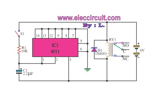
This circuit illustrates the use of the 4011 integrated circuit (IC) for a surge protection electronic circuit diagram. Features include the ability to delay the activation of other appliances connected to the output. The 4011 IC is a quad 2-input...
Color TV main power protection circuit The color TV main power protection circuit is designed to safeguard the television's power supply from various electrical anomalies, such as overvoltage, undervoltage, and short circuits. This circuit typically employs several components, including fuses,...
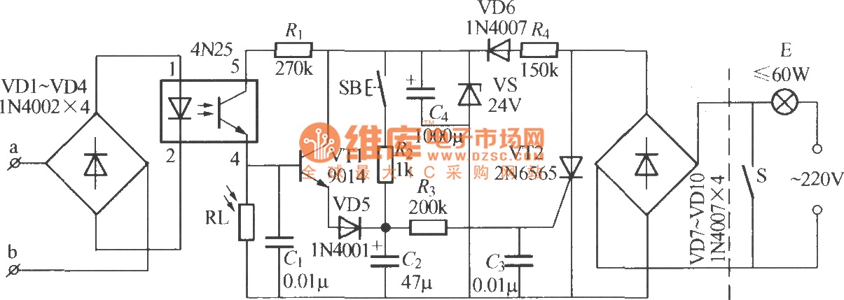
The diagram illustrates an automatic lighting control circuit activated by a telephone. At night, when the telephone rings or the user picks up the receiver, the light turns on. If the telephone stops ringing (when no one is listening)...
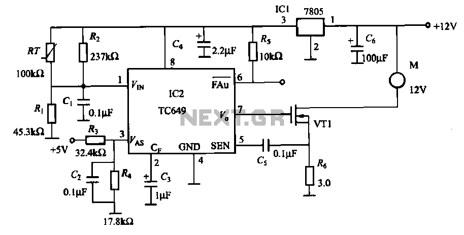
A motor is a heating device that can overheat, often due to accidents or overloads caused by excessive coil winding temperatures. The TC649 motor overheating protection and drive circuit, depicted in FIG. 1-9, utilizes an NTC thermistor (RT) positioned...
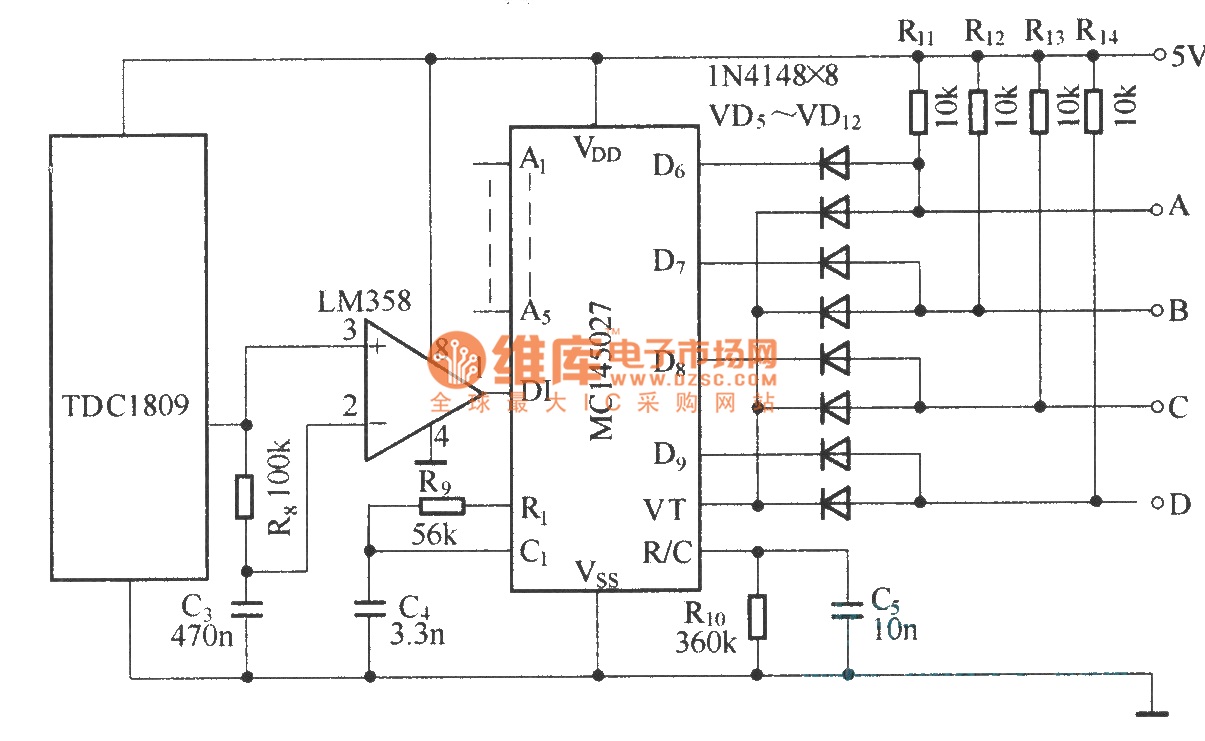
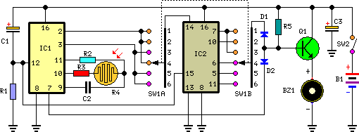
The TDC1808/TDC1809 is a pair of wireless remote control transmitter and receiver components. They utilize an internal antenna to transmit both digital and analog signals. These components are suitable for various wireless remote control devices. Key features include compact...