
power supply design 5v 7805 voltage regulator

The regulated 5V power supply typically consists of several key components: a transformer, a rectifier, a filter capacitor, a voltage regulator, and output capacitors.
1. **Transformer**: The transformer steps down the AC voltage from the mains to a lower AC voltage suitable for the power supply. A transformer with a secondary peak voltage of up to 35V is recommended to ensure adequate voltage for rectification and regulation. The choice of transformer affects both the physical size and heat dissipation of the overall circuit.
2. **Rectifier**: The rectifier converts the AC voltage output from the transformer into a pulsating DC voltage. A full-wave bridge rectifier is commonly used for this purpose, as it provides better efficiency and smoother output compared to a half-wave rectifier. The rectifier should be selected based on the peak inverse voltage (PIV) rating to handle the maximum voltage that can occur across its terminals.
3. **Filter Capacitor**: After rectification, the output voltage will still have ripples. A filter capacitor is employed to smooth out these ripples, providing a more stable DC voltage. The capacitance value must be chosen based on the load current and acceptable ripple voltage. A larger capacitance will yield a lower ripple but will also increase the physical size and cost of the capacitor.
4. **Voltage Regulator**: The voltage regulator is crucial for maintaining a steady output voltage of 5V despite variations in input voltage or load current. Linear voltage regulators, such as the LM7805, are commonly used for low-current applications. For higher efficiency, especially in battery-operated devices, a switching regulator may be preferred as it minimizes power loss and heat generation.
5. **Output Capacitors**: Additional output capacitors may be added to further stabilize the output voltage and improve transient response. These capacitors can help filter any high-frequency noise that may be present in the output.
In summary, the design of a regulated 5V power supply involves selecting appropriate components that work together to convert AC voltage to a stable DC output. Consideration must be given to the transformer specifications, rectification method, filtering requirements, and voltage regulation technique to ensure efficient and reliable performance.For making a power supply designing‚ of each and every component is essential. ‚Here I`m going to discuss the designing of ‚regulated 5V Power Supply. NOTE : Any transformer which supplies secondary peak voltage‚ up to35V can be used but as the voltage increases size of the transformer and power dissipation across regulator increases. 🔗 External reference
Related Circuits
To construct the circuit, follow the provided schematic. If assistance is required, do not hesitate to reach out for support. If there are difficulties in identifying the components... To build the circuit effectively, it is essential to adhere closely to...

One of the drawbacks of a three-pin voltage regulator is that the input voltage needs to be 2.5 to 3 V higher than the output voltage. This makes these integrated regulators unsuitable for battery power supplies. For instance, if...
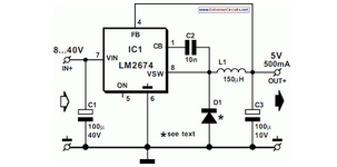
National Semiconductor has been producing and designing integrated circuits (ICs) for use in switch-mode power supplies for many years. The application of these devices is standard. National Semiconductor has established a significant presence in the design and manufacturing of integrated...
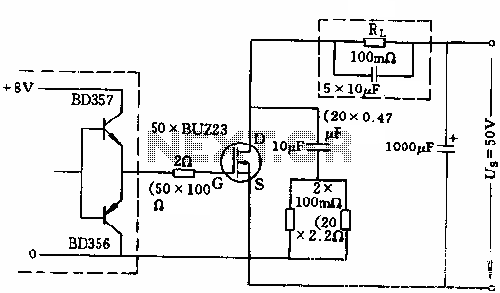
The circuit employs 50 BUZ23 field effect transistors (FETs) arranged in parallel, with a tube blocking voltage of 100V. The control power required is minimal, eliminating the risks associated with second breakdown and the positive temperature coefficient phenomenon in...
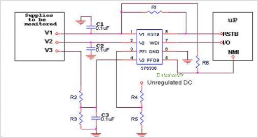
Introduction The SP6648 integrated synchronous boost regulator is a compact circuit that provides ultra-high efficiency drive current for an LED flashlight using a Luxeon I light source. The circuit is configured to deliver a constant output current of 350mA...
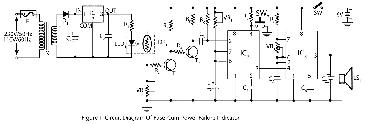
The Fuse Cum Power Failure Indicator utilizes a thermistor and a timer IC (NE555) in its circuit design. The circuit diagram includes a parts list for the fuse cum power failure indicator, which signals instances of power failure. The Fuse...