
Power Supply for Amlifiers [B]
![Power Supply for Amlifiers [B]](/uploads/133-54d133.gif "Power Supply for Amlifiers [B]")
The proposed power supply circuit for a 100W V-MOSFET amplifier is designed with multiple isolated power supply outputs to cater to different functional stages of the amplifier. The architecture includes dedicated power supplies for the following stages: the main power stage, the control stage, the preamplifier stage, and a protection stage. This modular approach allows for enhanced performance and flexibility in amplifier design.
The power stage is responsible for delivering the necessary current and voltage to drive the V-MOSFETs, ensuring that the amplifier can output up to 100W. The control stage typically includes voltage regulation and signal conditioning components, which are crucial for maintaining stable operation and minimizing distortion.
The preamplifier stage is designed to boost low-level audio signals before they are fed into the main amplification stage. It may include operational amplifiers and passive components to optimize signal gain and bandwidth. The protection stage is essential for safeguarding the amplifier and connected speakers from overcurrent and overheating conditions, often incorporating fuses, thermal sensors, and relay circuits.
The design allows for customization; users can choose to bypass certain sections of the power supply if they do not require specific functionalities. For instance, if the preamplifier and protection circuits are not needed, these can be omitted, simplifying the circuit and potentially reducing costs. Additionally, there is an option to implement separate power supplies for each channel, which can further isolate the channels from each other, reducing crosstalk and improving overall sound quality.
Overall, this proposed power supply design offers a versatile and robust solution for high-performance audio amplification, accommodating various user requirements and preferences while ensuring reliability and efficiency in operation.Proposed power supply for amplifier 100W v-mosfet [ 1 ] is what appears in the above form. It has separated supply for the various stages of supply, stage for power, stage for control, supply for preamplifier and for stage of protection. Whoever wants it can suppress departments or add a power supply for each channel, separating completely the channels between them.
For whoever it does not use the circuit of preamplifier and protection can suppress proportional coil.. 🔗 External reference
Related Circuits
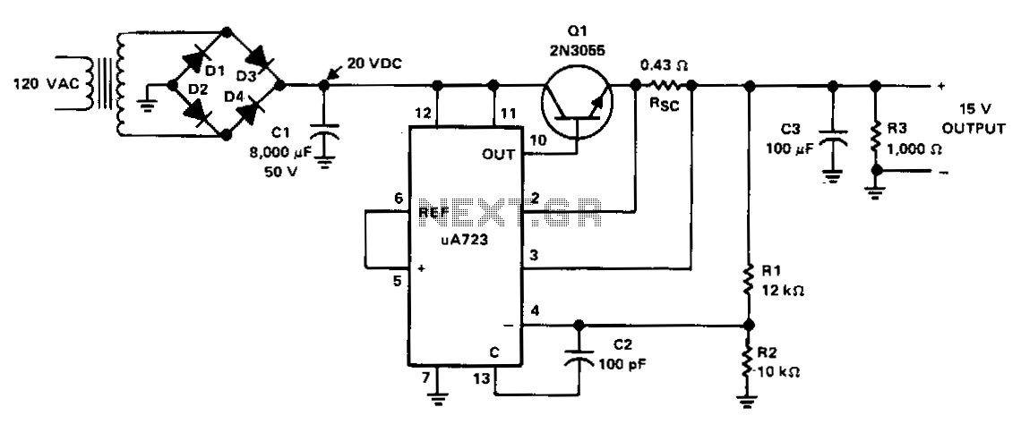
The power supply receives +20 VDC from the rectifier/filter section. This voltage is applied to pins 11 and 12 of the uA723 voltage regulator, as well as to the collector of the 2N3055 series-pass transistor. The output voltage is...
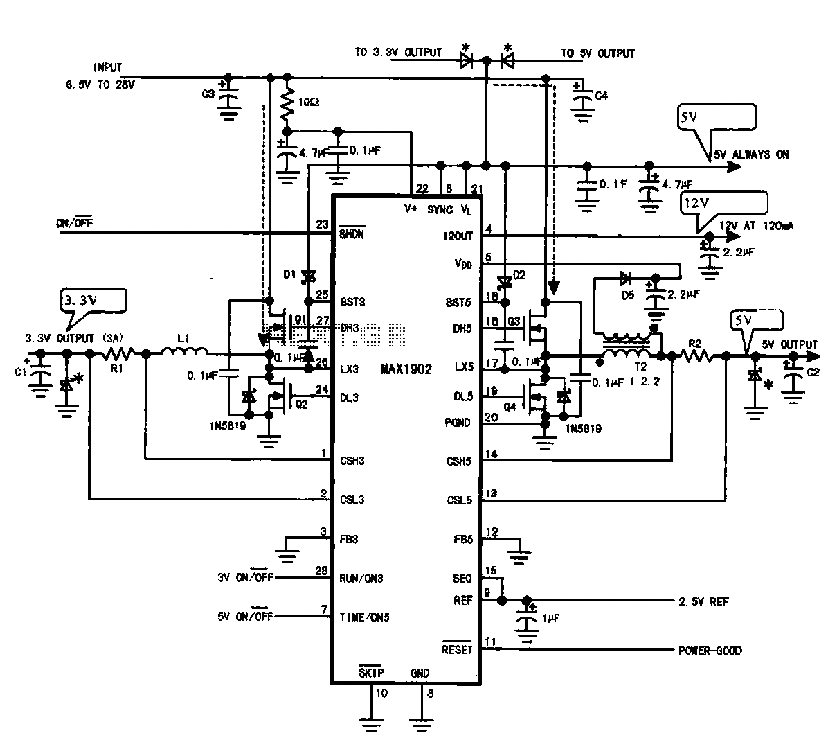
Multi-output power supply circuit (MAX1902). This circuit illustrates the power supply configuration for a notebook computer motherboard, utilizing the MAX1902 chip for power control. It is designed to convert the battery's DC voltage into multiple DC voltage outputs. The multi-output...
As readers may know, there are several power amplifier projects, including two that utilize integrated circuit (IC) power amplifiers, commonly referred to as power op-amps. Both of these projects have gained popularity, and this new project is not intended...
The circuit diagram illustrates a voltage regulator designed from discrete components to meet specific voltage requirements. It provides two sets of component values for output voltages of 6.3 V (upper) and 12.6 V (lower). The components used include BC547...
The W7800 is a positive integrated voltage regulator, while the F007 consists of an operational amplifier used in a power supply tracking application circuit. Some configurations utilize both positive and negative power supplies, with a negative supply necessary to...
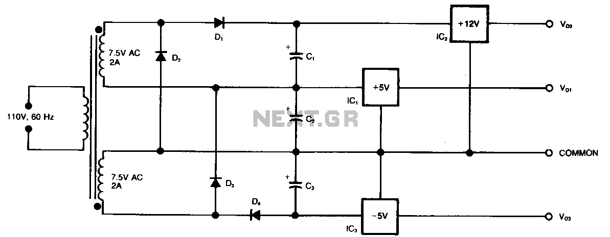
This circuit generates three supply voltages using a minimal number of components. Diodes D2 and D3 perform full-wave rectification, alternately charging capacitor C2 during both halves of the AC cycle. Meanwhile, diode D1 in conjunction with capacitor C1, and...