
Power Supply/OPUS Kill Switch

The switch panel design for the dashboard involves integrating four switches that can control various functions within the vehicle. Each switch should be clearly labeled to indicate its specific function, such as controlling lights, auxiliary power, or other electronic accessories.
The circuit design will include a power source, typically drawn from the vehicle’s battery, which is routed through a fuse for protection against overcurrent. Each switch will be connected in parallel to the power source, allowing for independent operation.
The wiring should be appropriately gauged to handle the expected current loads of the devices being controlled. For instance, if the switches control high-current devices, such as relays for lights, a heavier gauge wire should be used. Conversely, for low-power accessories, such as LED lights, a lighter gauge wire may suffice.
Additionally, an LED indicator can be incorporated next to each switch to provide visual feedback when the switch is activated. This involves connecting the LED in series with a current-limiting resistor to prevent excessive current flow, ensuring the longevity of the LED.
Mounting the switch panel securely within the dashboard is essential for safety and accessibility. The panel should be designed to fit within existing dashboard cutouts or mounted using brackets. Proper insulation and protection from moisture should also be considered to prevent corrosion and ensure reliable operation over time.
Overall, this switch panel serves as a practical solution for enhancing user control over various vehicle functions, contributing to a more efficient and organized dashboard layout.After searching for a few days i cant find a solution for this idea. Sorry for the wordy`ness I`m creating a switch panel in the dash containing 4.. 🔗 External reference
Related Circuits
The schematic illustrates a circuit designed to sense skin resistance and convert it into a functional switching signal. Touch switch contacts can be constructed from small metal plates, rivets, or nails, positioned closely on a non-conductive surface. The circuit...
If you are looking at this page, you probably feel like I did when I tried to run a self-powered PIC programmer with my notebook computer. Yes, the serial port was the ultra-low-power type and wouldn't provide enough current...
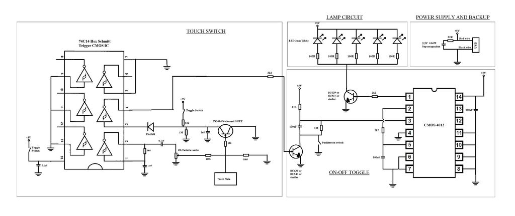
A touch switch for a USB-powered desk lamp is malfunctioning. The circuit diagram, layout, and pictures are provided below. The design incorporates circuits sourced from two websites, specifically the fourth circuit. The output of the touch switch is connected...
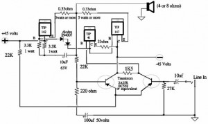
A 150W power amplifier circuit diagram utilizing power transistors TIP41, TIP142, and TIP147. The design is straightforward enough to construct without a printed circuit board (PCB). The power output range is approximately 100-150W. The 150W power amplifier circuit is designed...
The purpose of a DC power supply is to deliver the necessary level of DC power to a load by utilizing an AC supply at the input. Various applications demand different specifications; however, contemporary DC power supplies often ensure...

The soft start circuit refers to a power circuit where the output voltage gradually increases to a specified value, thereby protecting the load circuit from unwanted voltage surges. It can output a voltage of 24V and a current of...