
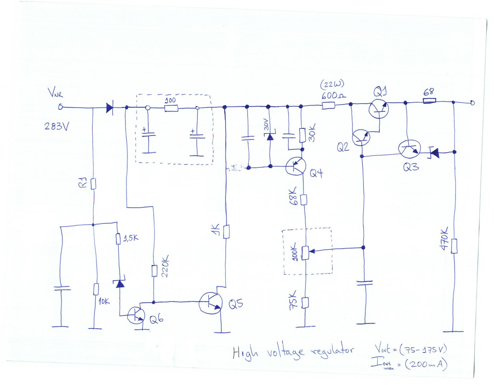
Power Up!

The AC to DC front stage boost converter operates by converting an alternating current (AC) input voltage into a direct current (DC) output voltage. In discontinuous mode, the inductor current does not flow continuously during each switching cycle, which can enhance efficiency under certain load conditions.
The design process begins with defining the specifications, including input voltage range, output voltage, output current, and efficiency targets. These parameters are critical in ensuring that the converter meets the intended application requirements.
Following the specification phase, a thorough analysis of the power factor correction (PFC) circuit is performed. The PFC circuit is essential in improving the power factor of the system, which minimizes the reactive power drawn from the AC supply and reduces harmonic distortion. This analysis typically involves evaluating various PFC topologies, such as the boost converter configuration, which is commonly used for this purpose due to its ability to step up voltage while providing inherent power factor correction.
Once the PFC circuit is established, the design of the boost converter stage commences. This stage includes selecting appropriate components such as the inductor, switch (typically a MOSFET), diode, and output capacitor. Each component must be carefully chosen to handle the expected voltage and current levels while minimizing losses. The control strategy for the boost converter is also developed at this stage, which may involve pulse width modulation (PWM) techniques to regulate the output voltage.
The final step in the design process involves the integration of a microcontroller. The microcontroller is programmed to manage the operation of the boost converter and PFC circuit, providing real-time monitoring and control. It can implement various algorithms to optimize performance, such as adjusting the duty cycle based on load conditions and ensuring stable operation across varying input voltages.
Overall, the design of an AC to DC front stage boost converter in discontinuous mode is a complex process that requires careful consideration of specifications, component selection, and control strategies to achieve efficient and reliable performance.The design of the AC to DC front stage boost converter in discontinuous mode underwent a few steps. First, the specifications where defined. Then, research was done and the basis power factor correction circuit was analyzed. Finally, the boost converter stage and the microcontroller were designed. 🔗 External reference
Related Circuits
The voltage requirement for the Solidus is significantly higher than what your circuit currently provides. The Solidus device operates at a voltage level that exceeds the specifications of the existing circuit. To accommodate this requirement, circuit modifications will need to...
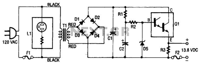
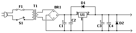
This regulated power supply consists of a step-down transformer T1, a full-wave rectifier bridge (D1 through D4), and a filtering regulator circuit made up of C1, C2, R1, R2, R8, D5, and Q1. When 120 Vac is provided, the...
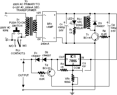
Self-switching power supply. One of the main features of the regulated power supply circuit being presented is that, although a fixed-voltage regulator LM7805 is used in the circuit, its. The self-switching power supply circuit utilizes the LM7805 voltage regulator to...
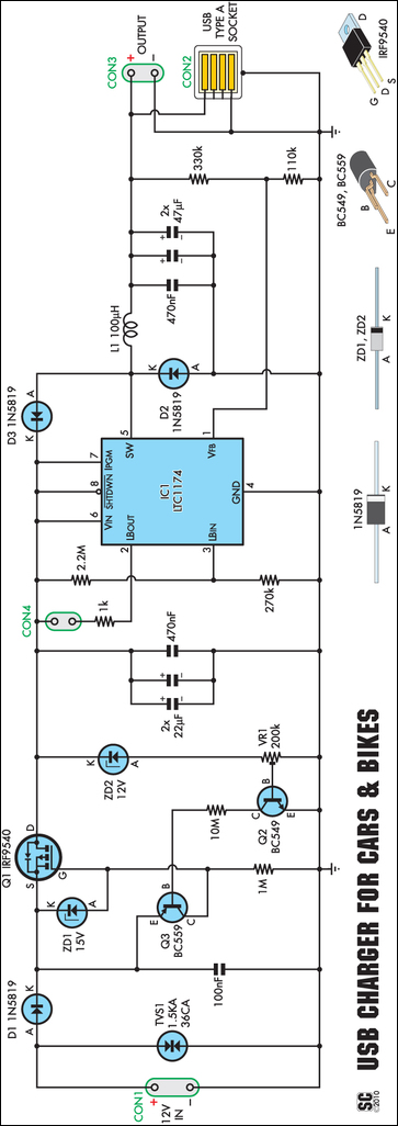
A regular charger was tested and found to consume 13mA with no load. It features an integrated power LED, which significantly contributes to standby current consumption. However, since the cigarette lighter socket is powered only when the engine is...
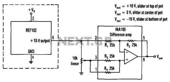
This circuit provides a precision voltage source that can be adjusted to produce zero, positive, and negative voltages, eliminating the need to reverse connections on the power supply. It allows for achieving exactly 0 V without any offset. The...
The fixed voltage power supply is useful in applications where an adjustable output is not required. This supply is simple, but very flexible as the voltage it outputs is dependent only on the regulator and transformer you choose. The...