
13.8Vdc 2A Regulated Power Supply Circuit

The described regulated power supply is a critical component in various electronic applications, providing a stable voltage output from a high-voltage AC source. The step-down transformer T1 plays a pivotal role in reducing the input voltage from 120 Vac to a safer 28 Vac, suitable for further processing. The full-wave rectifier bridge, composed of diodes D1 through D4, converts the alternating current (AC) output from the transformer into pulsating direct current (DC). This conversion is essential for powering DC devices.
Capacitor C1 functions as a smoothing capacitor, effectively filtering the pulsating DC output to provide a more stable DC voltage. It stores charge and releases it as needed, thereby reducing voltage ripple and ensuring a consistent output voltage. In conjunction with capacitor C2, which may be used for additional filtering or stability, the circuit can handle transient loads more effectively.
The Zener diode D5 is a crucial component in voltage regulation. By maintaining a constant voltage across the base of the Darlington transistor Q1, it ensures that the output voltage remains stable, even with variations in load current. This regulation is vital for sensitive electronic circuits that require a specific voltage for optimal performance. The Darlington pair configuration in Q1 allows for high current gain, making it suitable for driving larger loads while maintaining low output impedance.
Resistor R3, connected to the output, serves to limit the current and protect the circuit from overcurrent conditions. The presence of fuse F2 adds an additional layer of safety by disconnecting the circuit in the event of excessive current flow, thus preventing damage to the components.
Overall, this regulated power supply design is robust and reliable, suitable for various applications where stable DC voltage is required. Proper precautions must be observed when working with 120 Vac sources to ensure safety and prevent electrical hazards. This regulated power supply consists of step-down transformer Tl, a full-wave rectifier bridge (D1 through D4), and a filtering regulator circuit made up of Cl, C2, Rl, R2, R8, D5, and Ql, When 120 Vac is provided, the neon-lamp assembly LI lights up, and transformer Tl changes 120 Vac to about 28 Vac. The rectifier bridge, )1 through D4, rectifies the ac into pulsating dc, which is then filtered by Cl.
Capacitor Cl acts as a storage capacitor. Zener diode 1)5 keeps the voltage constant across the base of Darlington regulator Ql, causing constant voltage across resistor R3 and the (+) and (-) output terminals, where the load is connected. Fuse F2 is used to open (blow), if the current through the output terminals is too high. Make sure to take proper precautions when using projects powered by 120 Vac.
Related Circuits
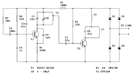
This is a basic telephone broadcaster or transmitter designed for eavesdropping on telephone conversations. The circuit can also function as a wireless telephone amplifier. A key feature of this phone transmitter is that it derives its power directly from...
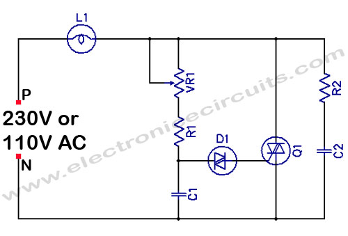
Filament Light Dimmer Circuit. This simple triac dimmer can be used to control incandescent filament lamps up to 200W. The circuit operates on standard AC voltage. The filament light dimmer circuit utilizes a TRIAC to control the power delivered to...
VOX is a voice-activated switch commonly used with microphones as an alternative to traditional push-button switches. The VOX can be connected to various audio equipment featuring an external speaker for coupling. The activation threshold is adjusted using the volume...
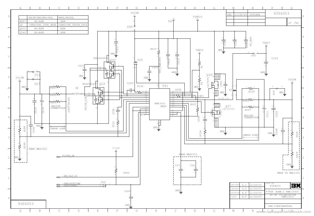
This is an IBM ThinkPad T40 power control circuit. This circuit is based on the MAX1631 IC, which is a multi-output, low-noise power supply. The IBM ThinkPad T40 power control circuit utilizes the MAX1631 integrated circuit (IC) to provide stable...
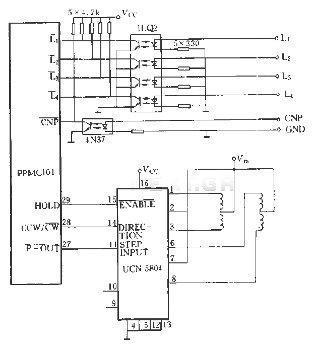
The PPMC external UChl 5804 demonstrates a four-phase stepping motor drive integrated circuit (IC) that is depicted in a downward motion. It utilizes the P-OUT, counterclockwise (ccw) / clockwise (cw), and HOLD outputs. The UCN5804 pins 9 and 10...
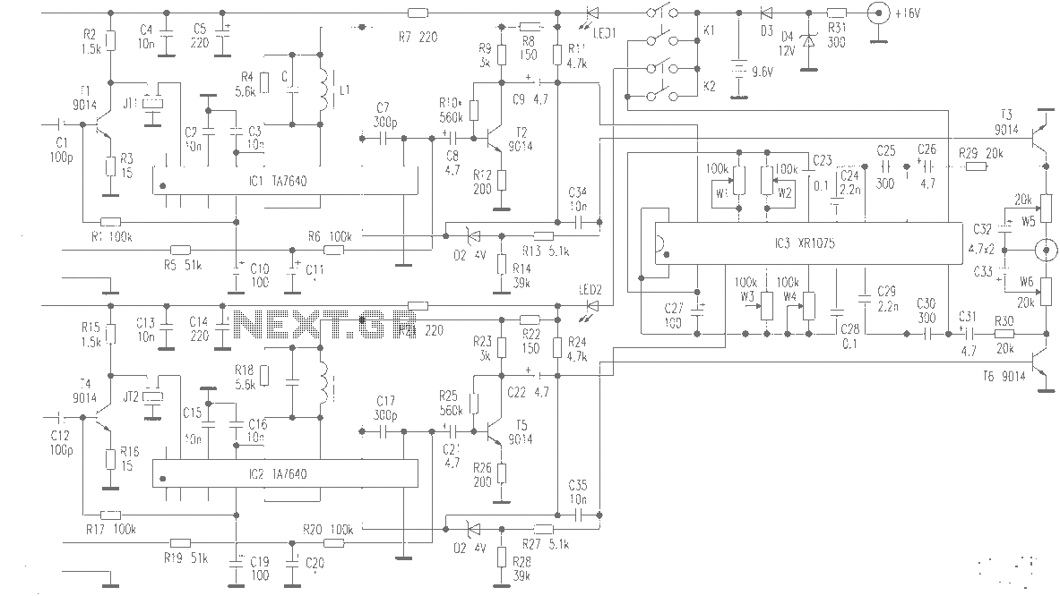
The production of high-quality wireless microphones is a common aspiration among enthusiasts, but achieving a high-performance receiver is challenging. This project explores the use of salvaged FM radio cassette players to enhance an XR1075 audio processor, leading to the...