
PREAMP

The described input stage employs a Burr-Brown INA121 differential amplifier, which is known for its high common-mode rejection ratio (CMRR) and low noise characteristics. The amplifier is configured to provide a gain of 10, which is suitable for amplifying small differential signals while minimizing the impact of common-mode noise. The DC coupling of the input stage allows for the direct processing of DC signals without the need for capacitive coupling, which can introduce phase shifts and limit bandwidth.
The tolerance for a differential DC offset of up to one volt indicates the robustness of the design in handling variations in electrode potentials, which is particularly relevant in applications such as bio-signal acquisition where electrode polarization can occur. Typical offsets in the range of a few hundred millivolts are acceptable, especially when using similar metal compositions for the electrodes, which helps to maintain the integrity of the differential measurement.
The circuit's common-mode rejection capability is contingent upon the performance of the Burr-Brown head-stage, ensuring that any common-mode signals present at the input are effectively rejected, allowing for accurate differential signal amplification. The modular design of the circuit permits flexibility; any op-amp can be selectively removed if its function is deemed unnecessary, streamlining the circuit for specific applications. For instance, in scenarios where a 60 Hz notch filter is not required, the output can be conveniently taken from the output of the third op-amp, thereby simplifying the design and potentially improving the overall signal processing efficiency.
This approach enhances the versatility of the circuit, making it adaptable to various signal processing needs while maintaining high performance in terms of noise rejection and signal integrity.The input stage is the most critical for common-mode rejection and noise. We used a Burr-Brown INA121 differential amplifier, set to a gain of 10. The input stage is DC coupled. With a 9-volt supply, a differential DC offset of up to about a volt is tolerable. Offsets of a few hundred millivolts are typical, assuming similar metals for the differe ntial electrodes. The common-mode rejection of the circuit is as good as the Burr-Brown head-stage. Any one of the opamps in the circuit can be removed (along with its supporting resistors and capacitors) if the function is not needed. For instance, if the 60 Hz notch filter is not needed, output may be taken from the output of the third op-amp.
🔗 External reference
Related Circuits

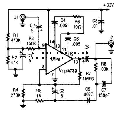
The goal is to construct a Gallium Arsenide Field Effect Transistor (GaAs FET) preamplifier that provides high gain and minimal noise using commonly available components. This preamp is designed to maintain stability across various source and load conditions. The...
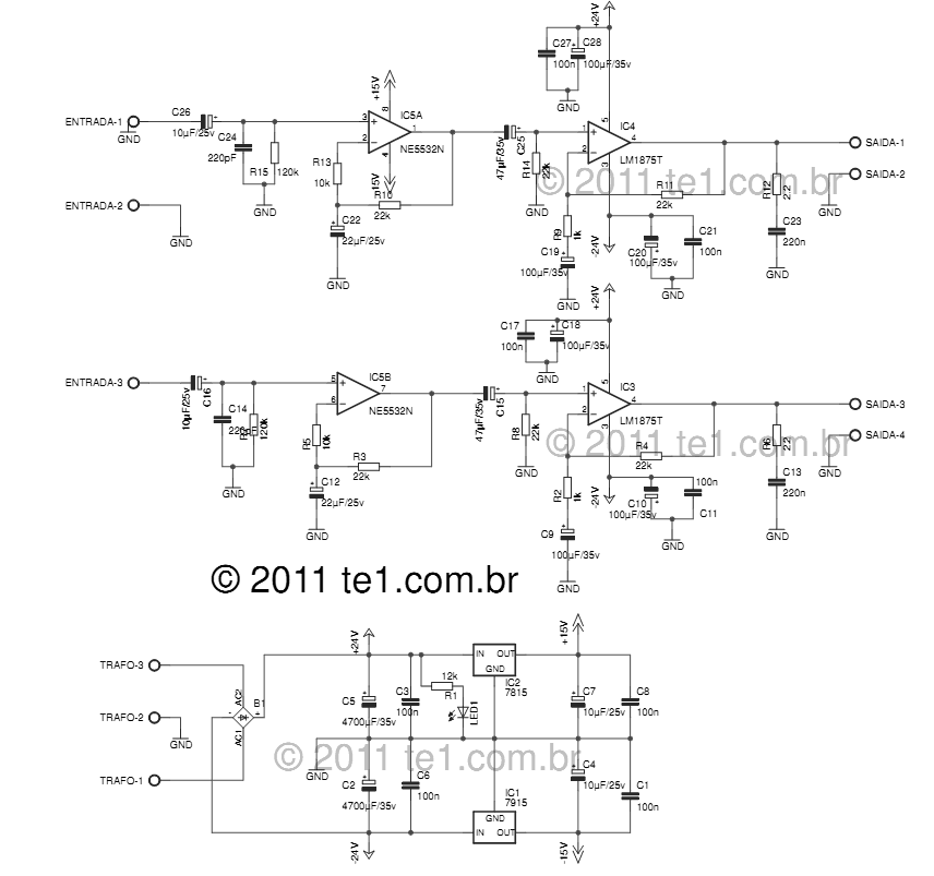
The LM1875 delivers 20 watts into a 4 or 8-ohm load on ±25V supplies. Using an 8-ohm load and ±30V supplies, over 30 watts of power may be delivered. The amplifier is designed to operate with a minimum of...
The circuit is fundamentally based on a well-tested simple microphone preamplifier design. A prototype of this circuit has been constructed and has demonstrated effective performance. The Sound Blaster soundcard series (SB16, SB32, AWE32, and AWE64) features a microphone input...
A fundamental component for audio applications, this circuit functions as a general-purpose preamplifier. It is recommended to utilize two circuits for stereo configurations. This audio preamplifier circuit is designed to amplify low-level audio signals, making it suitable for a variety...
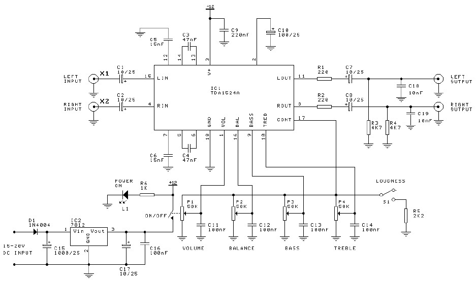
Preamplifier and tone control circuit based on the TDA1524A. The tone control circuit module is included in this preamplifier circuit, allowing for direct connection of the output channels to a stereo power audio amplifier circuit. This RIAA stereo preamplifier...
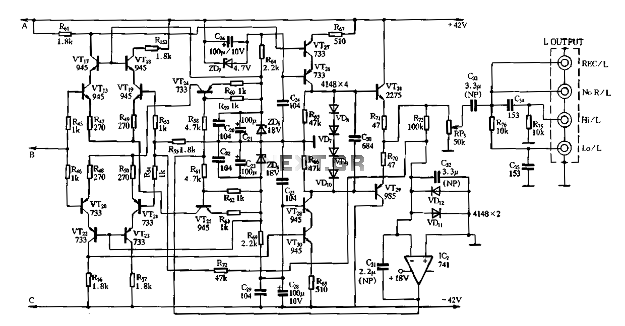
Figure 3-2 (b) represents the second half of the circuit, where transistors VT17 to VT31 are configured as power amplifiers and pre-amplifiers. This section is structurally identical to the operational integrated circuit IC2 and includes zero servos. The circuit...