
Printer Error Alarm

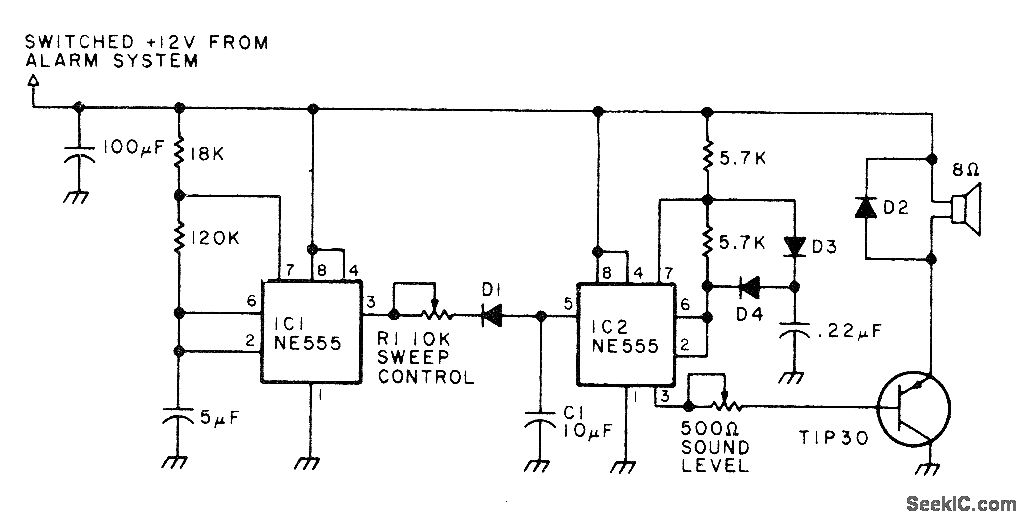
The circuit operates by monitoring the power state of the printer through a logic level signal that indicates whether the printer is powered on or off. The input signal is connected to a comparator or a microcontroller input pin that detects transitions in the logic level. When the printer is turned off, the input signal transitions from high to low (or vice versa), which is detected by the circuit.
Upon detecting this transition, the circuit activates an oscillator, which is configured to produce a square wave output. This output is responsible for generating an audible tone that serves as an alarm. The frequency and duty cycle of the oscillator can be adjusted to create different sound patterns, making the alarm more noticeable. The oscillator's output is typically fed to a small speaker or piezo buzzer, which converts the electrical signal into sound.
To ensure reliable operation, the circuit may include debounce circuitry to prevent false triggering due to noise or unintended fluctuations in the input signal. Additionally, a power supply circuit may be implemented to provide the necessary voltage and current to the oscillator and alarm components, ensuring they function correctly even during power fluctuations.
Overall, this circuit design effectively alerts users when a printer is powered down, providing a simple yet efficient solution for monitoring printer status. When a printer is shut down, this alarm sounds an alarm. The input can be either a high-to-low or low-to-high transitio n. This can be a logic level that corresponds with the printer being on or off. The oscillator produces an interrupted (on-off) tone.
Related Circuits
This circuit generates a high-intensity sound force field inside a vehicle, which is painful enough to deter a thief from entering the car after the alarm switch is triggered by opening the door. The circuit produces a square-wave output...
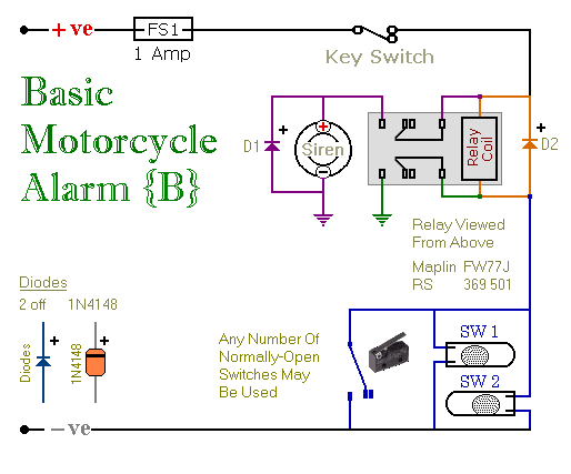
These are two easy-to-build relay-based alarms. They can be used to protect a motorcycle, but they have many additional applications. When using relays with 6-volt coils, they can safeguard a classic bike. Both alarms are compact, with completed boards...

This is the circuit diagram of a touch-activated alarm system that remains operational during power outages. The alarm system is triggered when someone touches the designated touch plate. A notable feature of this circuit is the automatic battery activator,...
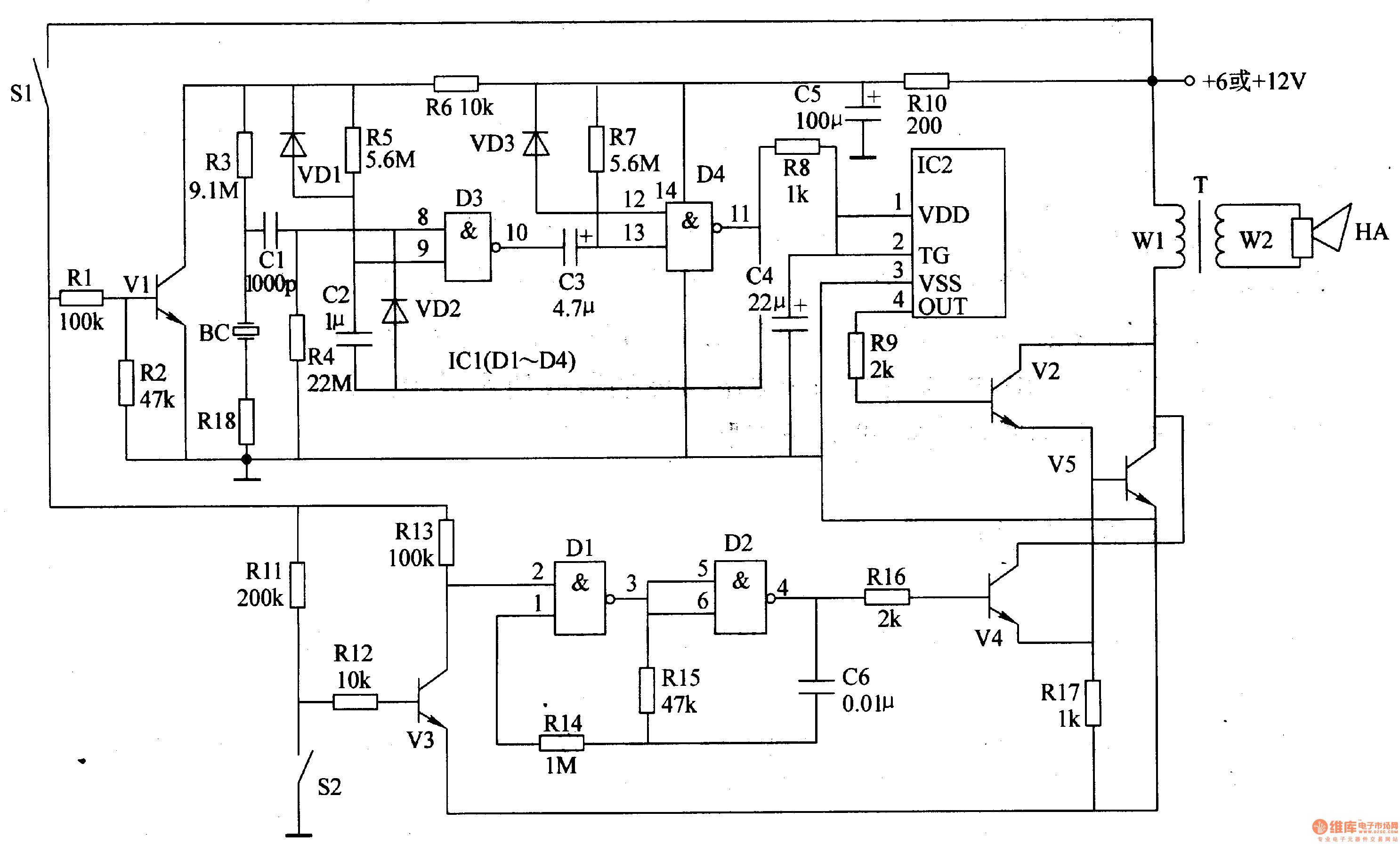
The motorcycle anti-theft alarm circuit consists of several components, including the anti-theft detection circuit, the control circuit, the sound generator, the audio oscillator, and the power amplifier output circuit, as illustrated in figure 7-91. The anti-theft detection circuit is...
Transistors are configured as a Darlington pair in this circuit. A thermistor is utilized to detect or sense heat. A 12K variable resistor is employed to adjust the activation of the buzzer at the desired temperature. The operation of...

This is a simple automatic light switch circuit designed for bedrooms. After construction, the input terminals of this circuit should be connected in parallel to the intended lighting fixture. The automatic light switch circuit utilizes a light-dependent resistor (LDR) as...