
Voltage Controlled Panner

The circuit described functions as a mono-to-stereo converter, allowing for the manipulation of audio signals in synthesizer applications. The primary component utilized is the dual operational amplifier, the LM1458, which consists of two op-amps in a single package. The design leverages the first op-amp to process the control voltage input, which ranges from 0 to 10V. This control voltage determines the panning of the audio signal between the left and right channels.
In the first stage, the control voltage is applied to the inverting input of the first op-amp. The op-amp configuration is set to invert the signal, effectively creating a phase shift that is necessary for controlling the gain of the right channel. The gain and offset adjustments are critical in ensuring that the audio signal maintains fidelity while being manipulated. The output of this stage is then directed to the second op-amp within the same package.
The second op-amp operates similarly, receiving the inverted signal from the first op-amp. This stage further processes the audio signal, ensuring that it is correctly balanced and panned according to the control voltage input. The output from this second op-amp can then be connected to the right channel of an audio output, while the original mono signal can be sent directly to the left channel.
To enhance the quality of the audio panning, a higher fidelity alternative can be implemented using the LM13700 dual transconductance amplifier. This component can be configured as a pair of voltage-controlled amplifiers (VCAs), offering improved performance characteristics, such as lower distortion and better dynamic range. The use of VCAs allows for more precise control over the audio signal, making it suitable for professional audio applications.
In summary, this circuit serves as a foundational design for converting mono audio signals to stereo, with the potential for upgrades to more sophisticated components to achieve higher audio quality. Its application in analog synthesizers highlights its relevance in both historical and modern electronic music production.This circuit is used to convert a mono audio signal into a stereo signal that can be panned between the left and right channel by a 0-10V control signal, it is intended for analog synthesizer systems. The circuit is mainly here for historical reasons, a higher quality panner may be built with the National Semiconductor LM13700 dual transconductance amplifier set up as a pair of voltage controlled amplifiers.
The control voltage is fed into the first half of a 1458 op-amp, this stage inverts the signal and sets the offset and gain for the right channel gain control circuit. This signal is then fed into the second half of the 1458 op-amp which inverts the v 🔗 External reference
Related Circuits
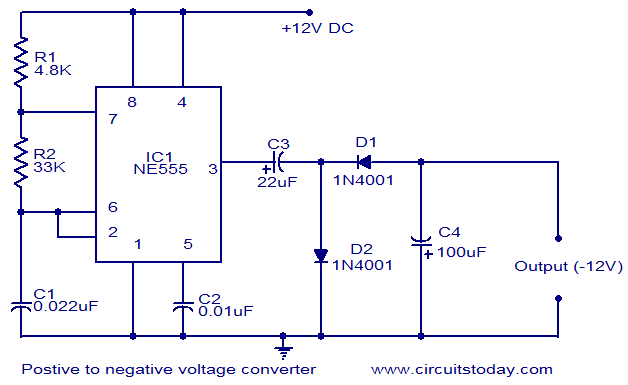
This circuit diagram illustrates the method for obtaining a negative voltage from a positive voltage supply. An additional benefit of this circuit is that the negative voltage, combined with the original positive supply, can be used to simulate a...
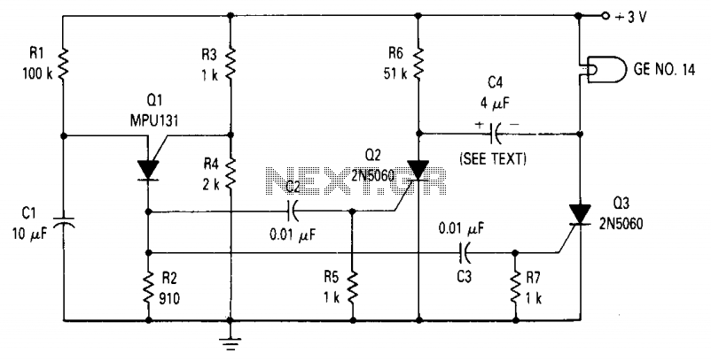
The circuit consists of a relaxation oscillator created by Q1 and an SCR flip-flop formed by Q2 and Q3. When the supply voltage is applied to the circuit, the timing capacitor C1 charges to the firing point of the...
This is a voltage doubling circuit built using the well-known timer IC 555. The circuit is straightforward and easy to construct. The construction is not critical. Rectifier diodes should be ultrafast (such as UF4004 or similar), or 1N4148 signal...
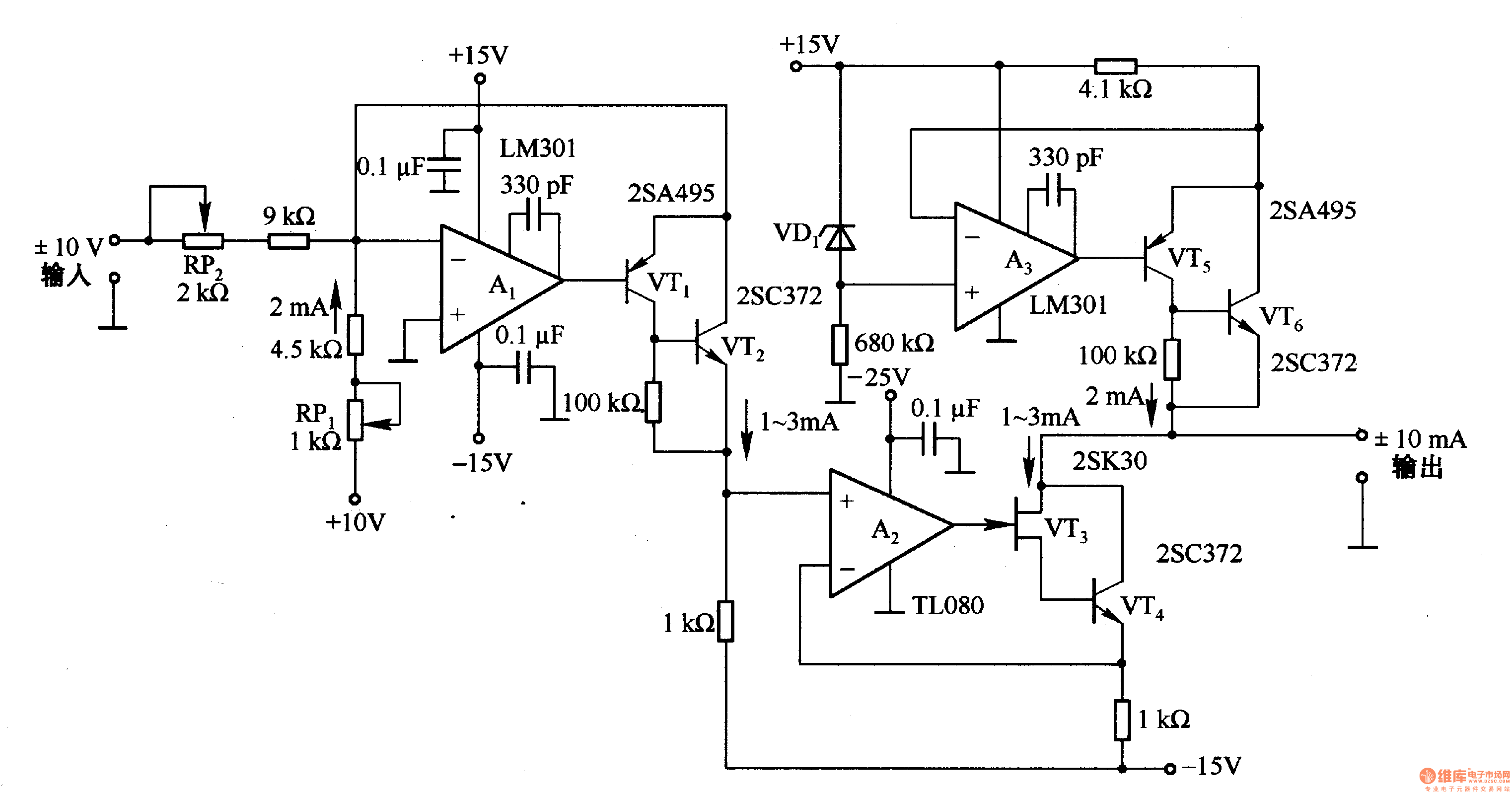
This circuit is designed for voltage-to-current conversion, specifically transforming a ±10V input voltage into a ±1mA output current. The conversion process is facilitated by operational amplifier A1 and transistors VT1 and VT2, which are responsible for altering the current...
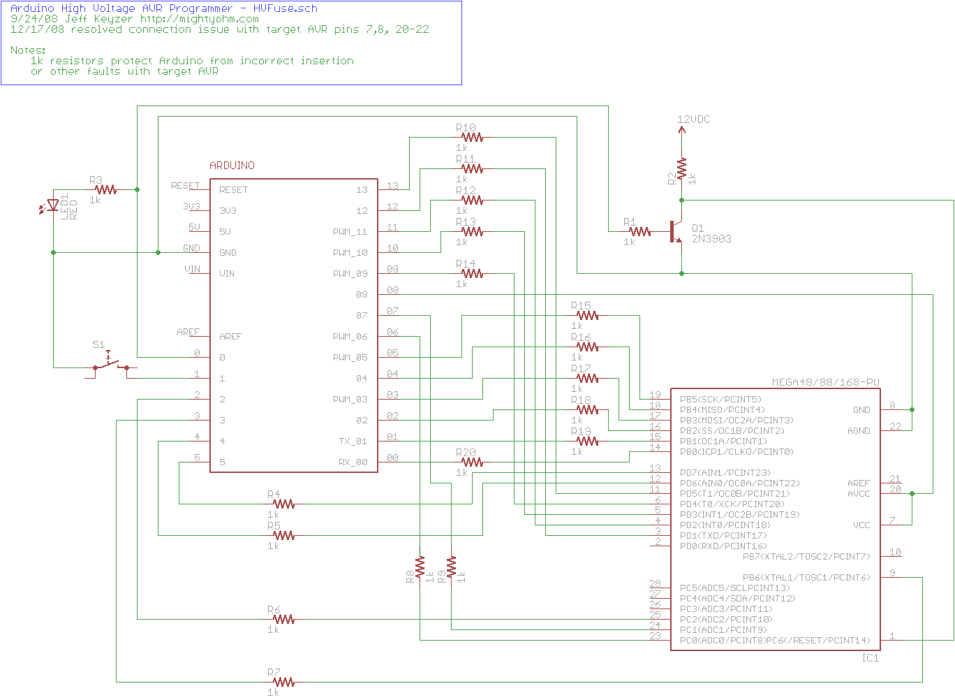
The project explains how to create a simple AVR High Voltage Programmer using Arduino. It can be utilized to fix or recover incorrectly fused AVR chips. The AVR High Voltage Programmer is designed to reprogram AVR microcontrollers that have been...
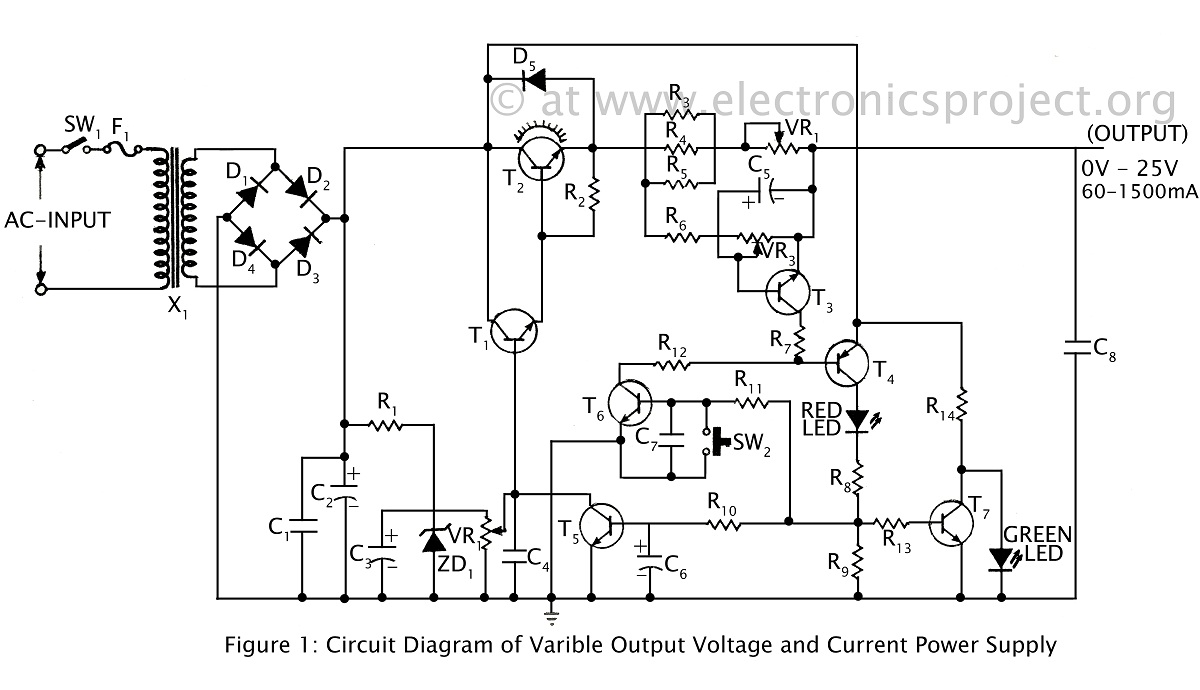
A ripple-free, short-circuit protected variable output voltage and current power supply is presented on this website as a verified project. The circuit diagram includes a description of various power supply circuits. This power supply circuit is designed to provide a...