
Programmable Current and Voltage Regulator for Battery Charger

The programmable current and voltage regulator circuit is designed to provide precise control over output voltage and current levels. This circuit typically employs an integrated voltage regulator, which can be adjusted to output a desired voltage level, while also incorporating an external current limiting feature to protect connected loads from excessive current.
The voltage regulator operates by maintaining a stable output voltage despite variations in input voltage or load conditions. The use of a variable resistor, designated as R2, allows for fine-tuning of the output voltage. By adjusting R2, users can set the desired voltage level according to the requirements of the application.
In addition to the voltage regulation, the current limiting aspect of the circuit is crucial for safeguarding sensitive components. This feature can be implemented using a current sensing resistor placed in series with the load. When the current exceeds a predefined threshold, the circuit can reduce the output voltage or shut down completely to prevent damage.
The overall design may also include additional components such as capacitors for stability, diodes for reverse polarity protection, and transistors for amplification or switching purposes, depending on the specific requirements of the application. Proper layout and thermal management are essential to ensure reliable operation, especially in high-current scenarios.
This circuit configuration is widely used in power supply designs, battery chargers, and various electronic devices requiring stable power delivery with adjustable parameters. Understanding the interplay between the voltage regulator, current sensing, and variable resistance is key to optimizing performance and reliability in practical implementations.This is a programmable current and voltage regulator circuit. It consist of a voltage regulator with external current limitation. The variable resistor R2 is.. 🔗 External reference
Related Circuits
The circuit utilizes a quad voltage comparator (LM339) as a basic bar graph meter to display the charge status of a 12-volt lead-acid battery. A 5-volt reference voltage is applied to each of the positive (+) inputs of the...
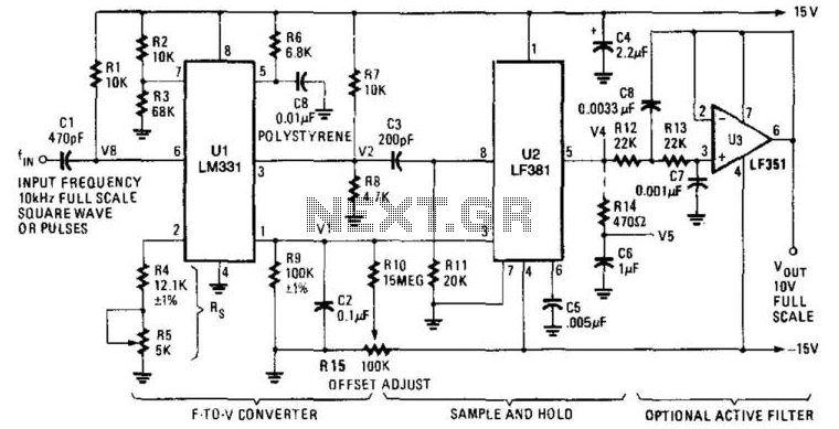
U1 is a frequency-to-voltage converter that feeds a sample-and-hold circuit utilizing an LF381 operational amplifier. An LF351 provides a 10-V maximum scale output. The circuit generates a 1-V output per kHz frequency. The described circuit employs a frequency-to-voltage conversion technique,...
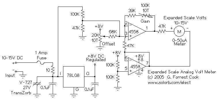
This circuit is used to measure the voltage on a 12V (nominal) lead acid rechargeable battery system. It was specifically designed for use in solar powered systems, but is general enough that it can be used for automotive or...

If a lead-acid battery is not used for an extended period, it experiences self-discharge at a rate of 4% per week at 27 degrees Celsius. For instance, a 125 Ah tubular battery discharges at a rate of 5 Amps...

This simple circuit consists of a transformer, two diodes, a capacitor, and an ammeter. To charge a battery, connect the positive and negative terminals of the circuit to the corresponding terminals of the battery. When the battery is not...
The charger is built around a LM317 adjustable regulator. The charge starts when a battery is connected between pins JP1-JP4 or JP2-JP4 or JP3-JP4. For example, if a battery is connected to JP1-JP4 pins then the current that flows...