
Programmable Identifier

The described circuit is integral to the operation of an amateur or experimental radio beacon, facilitating the generation of callsigns or messages that are stored in an Electrically Programmable Read-Only Memory (EPROM). The core of this circuit is the CD4020 CMOS counter, which is a versatile binary counter capable of counting in binary up to 14 bits. This counter is driven by an RC clock circuit, which provides the necessary timing signals for operation.
The RC clock circuit typically consists of a resistor (R) and a capacitor (C) configured in a way that determines the frequency of the clock pulses. The frequency can be adjusted by varying the values of R and C, allowing for flexibility in the timing of the message transmission. The output frequency of the clock signal directly influences how quickly the EPROM is accessed, thus controlling the rate at which different callsigns or messages are transmitted.
The CD4020 counter's output is connected to the EPROM, which stores the programmed callsigns or messages. As the counter increments, it generates address signals that are sent to the EPROM. The EPROM responds by outputting the corresponding data stored at those addresses. The serial data output is available at pin 9 of the CD4020, which can be connected to a suitable transmission circuit to send the generated callsign or message over the air.
This configuration allows for a simple yet effective method of generating variable messages for radio beacons, making it ideal for amateur radio enthusiasts and experimental applications. The modular nature of the components used in this circuit also allows for easy modifications and expansions, enabling users to customize the operation according to their specific needs. Used on an amateur or experimental radio beacon, the above ID circuit will generate any callsign or message program med into the EPROM. A CD4020 CMOS counter is driven by an RC clock circuit. This addresses the EPROM, and serial data is available at pin 9.
Related Circuits
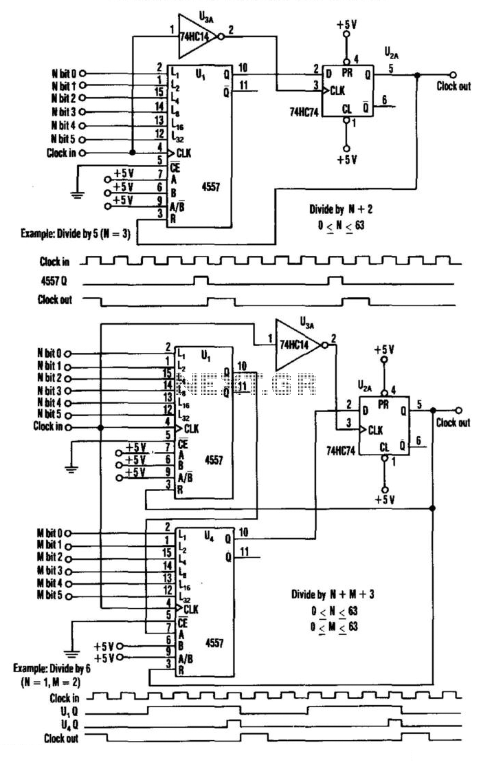
This divider utilizes a variable-length shift register, a type-D flip-flop, and an inverter. The clock signal is connected to the clock input of the flip-flop, while the output of the shift register is connected to the D input of...
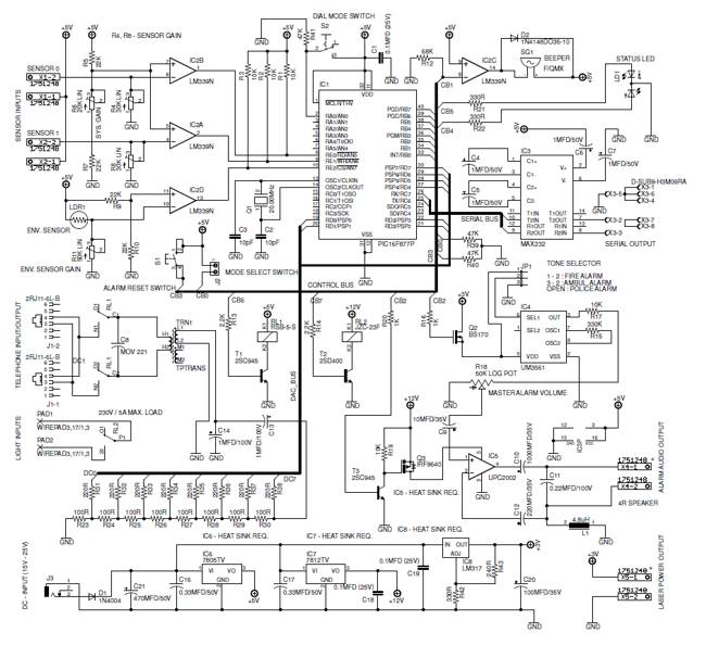
A low-cost, high-performance programmable home security system utilizing a few LDRs as input sensors. When the sensors are triggered, the system can dial a user-specified phone number using a built-in DTMF generator and activate a high-power audio alarm and...
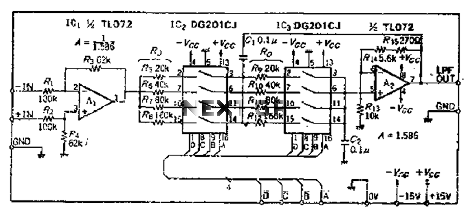
The circuit primarily consists of two Butterworth filters, designed to create a feedback amplifier with a gain of approximately 0.707. It features a differential input amplifier, where one input is grounded, resulting in a single input terminal. The attenuation...
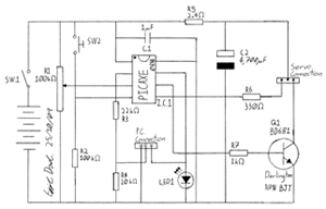
This project involves creating a programmable camera controller using basic hand tools and a digital camera. By utilizing components that are commonly found at home, the overall costs can be minimized. A servomotor can be repurposed from a radio-controlled...
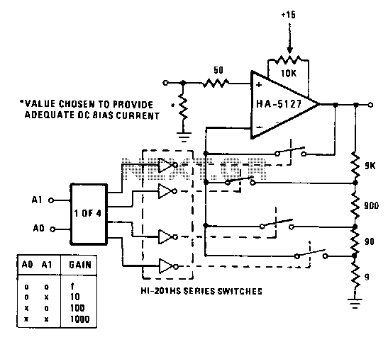
A circuit may often be required to perform multiple functions. In these cases, the variable gain configuration of the circuit can be particularly advantageous. This programmable gain stage utilizes CMOS analog switches to modify the feedback amount, thereby adjusting...
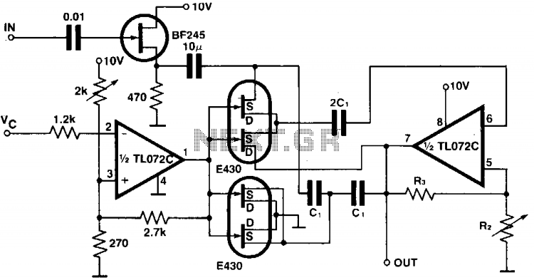
The circuit provides a programmable bandpass filter where both the cutoff frequency and gain (A) can be controlled independently. In the twin-T bridge configuration, the resistors R and R/2 are replaced by two double FETs, with the channel resistance...