
INA321 OPA340 composed output buffer circuit 322

The circuit employs the OPA340 as a voltage follower to enhance the output drive capability of the INA321/322 instrumentation amplifiers. The configuration ensures that the output voltage closely follows the input voltage, which is essential for maintaining signal integrity while driving lower impedance loads.
The INA321/322 series is designed for precision applications with a focus on high common-mode rejection and low offset voltage. The recommended load impedance of 10k ohms or greater helps to ensure that the output stage operates within its optimal range, where linearity and performance are maximized. When the load impedance is reduced below this threshold, the output current increases, which may lead to potential distortion or performance degradation if the circuit is not designed to handle such conditions.
The OPA340's output stage has a limitation, where the maximum output swing is 50mV below the supply voltage. This characteristic is critical in applications that require precise voltage levels, as it defines the maximum output voltage that can be achieved. The ability of the OPA340 to drive loads up to 600 ohms makes it suitable for a variety of applications, including those that require interfacing with other analog components or driving low-impedance inputs.
In summary, the combination of the INA321/322 and the OPA340 in this configuration provides a robust solution for applications requiring high precision and reliable output drive capabilities, particularly in environments where load conditions may vary. As shown in FIG constituted by OPA340 INA321/322 output buffer circuit. INA321/322 optimum load impedance 10k or more. When the load impedance decreases, the output current wil l increase. Op amp OPA340 constitute a voltage follower as an output buffer circuit for increasing the output drive capability INA321/322s. OPA340 maximum output voltage swing is lower than the supply voltage 50mV, able to drive up to 600 load.
Related Circuits
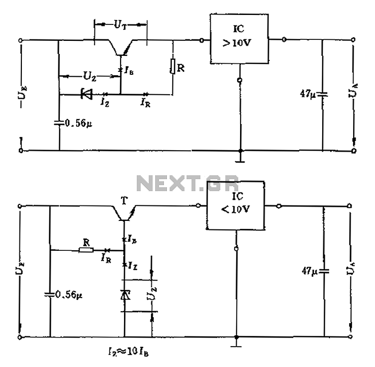
The voltage equation Ue = Ut + Ur + Ua indicates that the transistor voltage Ut will determine the maximum output voltage Ua. Additionally, Ur must be 2V. The voltage regulator's voltage value depends on the selection of Uz....
The following file is an application note describing the two stages of an electronic ballast for a 250 W HID metal halide lamp. The components include. The application note outlines a two-stage electronic ballast designed specifically for a 250 W...
This light-sensitive automatic light switch circuit is designed to be connected to the main 220V supply. The circuit will activate a 220V lamp during nighttime. The light-sensitive automatic light switch circuit operates by utilizing a light-dependent resistor (LDR) to detect...
The following circuit illustrates a fully linear diode sensor circuit diagram. This circuit is based on the A748 integrated circuit (IC). Features include the use of an operational amplifier (op-amp). The fully linear diode sensor circuit utilizes the A748 IC...
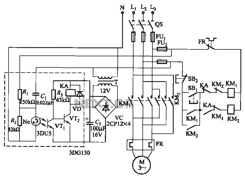
In certain applications, it is crucial to allow a motor to operate in only one specific direction, even when the power supply phase sequence is incorrect. This situation may arise due to external factors, such as incorrect wiring after...
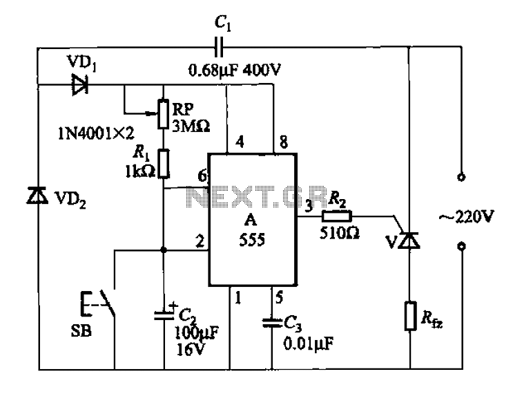
The 555 integrated circuit (IC) is utilized in a delay circuit configuration. It transitions from a high to a low output state when a button (SB) is pressed. The output remains high for a specified delay period before transitioning...