
Pulse Delay Generator

The delayed pulse generator circuit is designed to produce a pulse output after a specified delay, allowing for precise timing control in various applications. This circuit typically employs a combination of resistors, capacitors, and a timing component such as a 555 timer IC or a microcontroller to achieve the desired delay and pulse characteristics.
The operation begins with the charging of a capacitor through a resistor, which determines the delay period. The time constant, defined by the product of the resistor (R) and capacitor (C) values (τ = R × C), dictates how long it takes for the capacitor to reach a certain voltage level, triggering the output pulse. Once the voltage across the capacitor exceeds a predefined threshold, the output transitions from low to high, generating the pulse.
Additionally, the pulse width can be adjusted by modifying the resistor and capacitor values, allowing for independent control over the pulse rate and duration. This flexibility makes the delayed pulse generator suitable for applications such as timing circuits, signal modulation, and as a trigger for other electronic devices.
In practical implementations, the circuit may include features such as adjustable delay settings, output indicators, or protection components to enhance reliability and user interaction. Overall, the delayed pulse generator is a versatile component in electronic design, providing essential timing functions across a wide range of systems.This circuit is a Delayed Pulse Generator that is used to provide pulse rate and independent control of initial delay. The pulse generator of this circuit is. 🔗 External reference
Related Circuits
The control of electric motors is a topic of interest for those involved in Meccano model building. Each model has specific motor requirements concerning available space, motor power, speed, frequency of start and stop, and the necessity for reduction...
This circuit generates dual-tone bell sounds similar to those found in standard doorbell units. It is applicable in various contexts beyond doorbells. The circuit, as depicted in the diagram, produces a "Ding-tone" when switch P1 is pressed and a...

This circuit represents a waveform generator, which is highly beneficial for electronic experiments and design. It primarily generates sine wave oscillations, but the circuit can be modified to produce triangle or square wave functions. The circuit is based on...
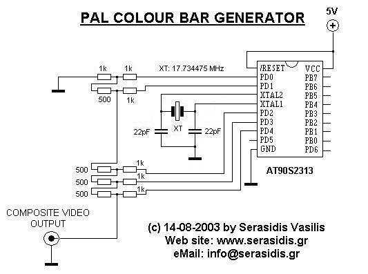
The first idea was to work with an 8.867238 MHz crystal (2 times the color carrier). When reading more about PAL video composite signal creation, it was found that to produce colors entirely in software, one must create the...
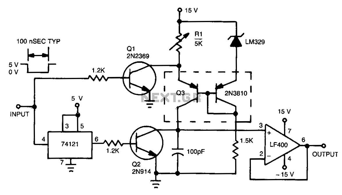
This circuit functions by charging a small capacitor using a constant-current source when a measurable pulse is present. The dual PNP transistor Q3 acts as the current source, with its output current determined by dividing the LM329 reference voltage...
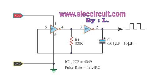
The inverter CMOS digital IC CD4049 is utilized to design a square wave oscillator generator. The CD4049 is a hex inverting buffer, which means it contains six independent inverters that can be used to generate square wave signals. This IC...