
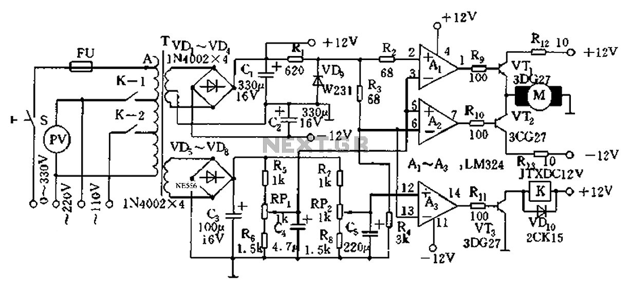
Pulse Width to Analog Voltage Demodulator

The pulse width to analog demodulator circuit is designed to convert pulse-width modulated (PWM) signals into corresponding analog voltage levels. This conversion is essential in various applications, such as motor control, audio signal processing, and sensor interfacing, where a PWM signal needs to be translated into a usable analog format.
The core components of the circuit typically include an operational amplifier (op-amp), resistors, and capacitors. The PWM input signal is fed into the circuit, where the op-amp is configured to integrate the pulse widths over a specified time period. This integration process effectively averages the PWM signal, resulting in a smooth analog output voltage that corresponds to the duty cycle of the input pulses.
The resistors in the circuit can be used to set the gain of the op-amp, allowing for adjustments in the output voltage range. Capacitors are employed to filter high-frequency noise and stabilize the output, ensuring that the analog signal is clean and representative of the PWM input.
In summary, the pulse width to analog demodulator circuit serves as a crucial interface between digital control signals and analog systems, enabling effective signal processing and control in electronic applications.This is a schematic diagram of a pulse width to analog demodulator circuit. This circuit is used to demodulate the pulse width to analog voltage level. With. 🔗 External reference
Related Circuits
Automatic AC voltage regulator circuit TXD1742 with continuous adjustment. The TXD1742 is an automatic AC voltage regulator circuit designed to provide continuous voltage adjustment, ensuring stable output voltage in varying load conditions. This circuit is particularly useful in applications where...
There are two regulator circuits that utilize the L200 integrated circuit from SGS-Thomson to regulate voltage and current. In circuit Fig. 1, the output voltage can be adjusted using the variable resistor RV1. In Fig. 2, both output voltage...
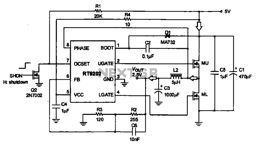
A 5V to 2.5V voltage regulator circuit is designed for use in computer motherboards. At its core, this circuit utilizes the RT9202 power management chip. The RT9202 functions as a switching pulse generating circuit, which, upon startup, converts a...
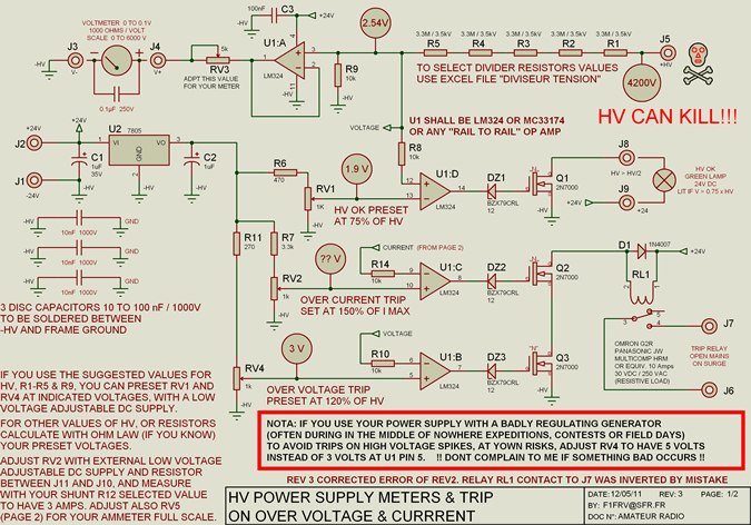
High voltage resistors for the high voltage divider are SFERNICE or PHILIPS type VR37 (3.5 kV - 0.4 W). They are not expensive (even if they are sold in quantities of 25 or 50 units), and it is always...
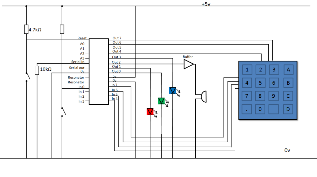
A keypad lock is being developed using a PIC microcontroller and a passive keypad with 8 pins, consisting of 4 input and 4 output pins. Each input pin corresponds to a row of numbers on a 4x4 keypad, while...
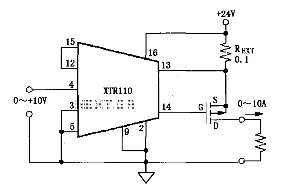
When the output current exceeds 40mA, the XTR110 requires the use of an external resistor (REXT) instead of the internal 50-ohm resistor (R9). REXT should be connected between pin 13 and pin 1. The value of REXT is determined...