
PULSE POSITION MODULATOR

The circuit employs a timer IC, such as the 555 timer, configured in an astable mode to generate a continuous square wave output. In this configuration, the timer operates without any stable state, producing a waveform that oscillates between high and low states. The frequency and duty cycle of the output waveform are determined by the resistors and capacitors connected to the timer.
A key feature of this design is the application of a modulating signal to the control voltage terminal of the timer. This allows for dynamic adjustment of the pulse width, effectively modulating the output signal based on the input signal characteristics. The control voltage influences the threshold and trigger levels of the timer, which in turn alters the timing intervals of the output pulses.
The circuit can be further enhanced by incorporating additional components such as potentiometers for fine-tuning the resistance values, allowing for more precise control over the timing characteristics. Capacitors with different values can also be tested to observe their effect on the frequency and duty cycle of the output waveform.
Overall, this astable timer circuit with a modulating control voltage provides a versatile platform for generating variable pulse-width modulation (PWM) signals suitable for applications such as motor control, light dimming, and audio signal processing.This application uses the timer connected for astable (free-running) operation, with a modulating signal again applied to the control voltage terminal. The pulse position varies with the modulating signal, since the threshold voltage and the time delay is varied.
🔗 External reference
Related Circuits
Designing various electronic circuit systems (synthesizer, modem, decoder, data converter, etc.) often requires a frequency modulator subsystem. An FM modulator is a crucial component in these systems. An FM modulator is an electronic device that encodes information in a carrier...

Two integrated circuit (IC) RF modulators are utilized to convert a suitable baseband video and audio signal into a low VHF modulated carrier, specifically channels 2 through 6 in the U.S. and channels 1 through 3 in Japan. The...
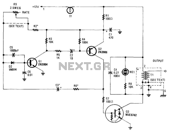
This high-voltage pulse supply generates pulses up to 30 kV. Q1 and Q2 form a multivibrator in conjunction with peripheral components R1 through R6, and C1, C2, C3, C5, C6, and D2. R9 adjusts the pulse repetition rate, while...
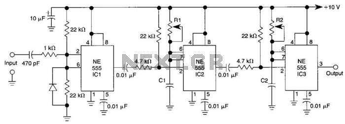
Three 555 IC timers are utilized in this circuit to create a simple delayed-pulse generator. IC1 functions as a waveform shaper to generate a rectangular waveform. IC2 generates a delaying pulse that triggers IC3 on the trailing edge of...
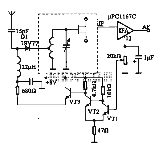
This circuit illustrates an FM modulator with a strong and weak signal switching mechanism. The circuit diagram 3-14 (a) depicts mechanical switches, including a worker selector switch that allows for signal strength selection. Figure 3-14 (b) demonstrates the implementation...
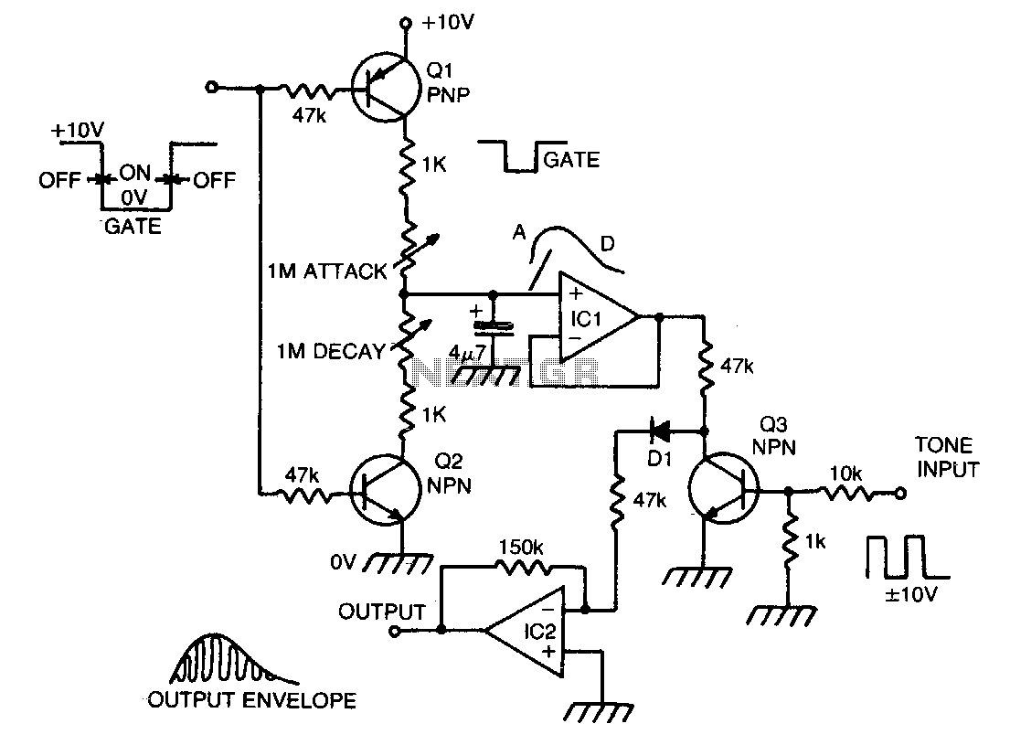
When a gate voltage is applied, Q1 is activated, and capacitor C is charged through the attack potentiometer in series with a 1 KΩ resistor, which varies the attack time constant. A fast attack results in a percussive sound,...