
PWM Dimmer/Motor Speed Controller

First, an explanation of PWM is necessary. As the potentiometer is rotated clockwise, the input voltage changes linearly. Initially, the voltage is low enough that the comparator output produces narrow spikes, causing the MOSFET to turn on for brief intervals. The average current is low, resulting in dim LEDs or a slow-running motor. As the input voltage from the potentiometer increases, the MOSFET remains on for longer durations, thereby increasing power to the load. The PWM principle is illustrated in a waveform diagram, where the red trace represents the triangle wave reference voltage and the green trace corresponds to the potentiometer voltage. When the input voltage exceeds the reference voltage, the MOSFET activates, allowing current to flow to the load. Due to the relatively high frequency (approximately 600 Hz), flickering in the LEDs is not noticeable, although an audible tone may be present from a PWM-controlled motor. The PWM signal is depicted in blue. The average current through the load is determined by the ratio of on-time to off-time, achieving an average current that is half of what would be drawn under direct current (DC) conditions.
The circuit design includes an oscillator (U1) that generates a triangular waveform. Resistors R4 and R5 set a half-voltage reference, enabling the op-amps to operate around a 6V center voltage. U2A functions as an amplifier, producing a 10V peak-to-peak triangle wave that is utilized by the comparator (U2B). This comparator compares the voltage from the potentiometer with the triangle wave. At zero input voltage, the comparator output remains low, keeping the MOSFET off, which represents the zero setting. In practice, the reference triangle waveform ranges from approximately 1.5V to 9.5V, resulting in a small inactive range at both ends of the potentiometer's rotation; this is a standard feature that ensures a clear off and maximum setting. This range allows for the use of an industry-standard 0-10V DC control signal for lighting applications, compatible with various home automation systems that can provide 0-10V modules to control the dimmer.
For applications requiring motor speed control, a high-current fast recovery diode is necessary. While a 1N4004 diode is suitable for dimming applications, a diode such as the HFA15TB60PBF ultra-fast HEXFRED diode is recommended for motor speed control, capable of handling up to 15A continuous current, making it adequate for motors drawing up to 30A. Although the dimmer circuit can be constructed on veroboard, it is advisable to use a PCB for ease of assembly and reliability. The PCB, measuring 53 x 37 mm, accommodates all components, including screw terminals, and features double-sided construction with plated-through holes and solder masks. A heatsink is required for the MOSFET unless used solely for light loads, necessitating insulation from the heatsink since the transistor's case serves as the drain (PWM output). For high current and potential high temperatures, a larger heatsink may be required. Although the MOSFET typically dissipates around 2W at 10A, excessive heat can lead to thermal runaway and component failure. An IGBT (Insulated Gate Bipolar Transistor) may also be employed, as they generally share similar pinouts and do not experience the same thermal issues as MOSFETs.
The IRF540 MOSFET is a suitable choice, rated for 27A, providing a significant safety margin. Many other MOSFETs rated at 10A or more, with a maximum voltage exceeding 20V, are also acceptable. The circuit should be connected to a compatible 12V power supply. During initial power-up, a 100-ohm safety resistor should be placed in series with the positive supply to limit current in the event of wiring errors. The total current drain is approximately 2.5mA with the potentiometer fully off, increasing to 12.5mA when fully on. Most of this current is consumed by the LED, which is powered by the PWM supply, allowing for visual confirmation of circuit functionality without connecting a load. When powering on, ensure the potentiometer is fully anti-clockwise (minimum). The voltage across the safety resistor should not exceed 0.25V at minimum and should rise to 1.25V at maximum. If these conditions are met, the safety resistor can be removed, and a load can be connected. High-intensity LED strip lights may draw up to approximately 1.5A each, and this dimmer circuit is capable of driving up to ten such strips, contingent on the power supply's capabilities and the size of the MOSFET's heatsink.This is yet another project born of necessity. It`s a simple circuit, but does exactly what it`s designed to do - dim LED lights or control the speed of 12V DC motors. The circuit uses PWM to regulate the effective or average current through the LED array, 12V incandescent lamp (such as a car headlight bulb) or DC motor.
The only difference betwee n the two modes of operation is the addition of a power diode for motor speed control, although a small diode should be used for dimmers too, in case long leads are used which will create an inductive back EMF when the MOSFET switches off. The photo shows what a completed board looks like. Dimensions are 53 x 37mm, so it`s possible to install it into quite small spaces. The parts used are readily available, and many subsitiutions are available for both the MOSFET and power diode (the latter is only needed for motor speed control).
The opamps should not be substituted, because the ones used were chosen for low power and their ability to swing the output to the negative supply rail. Note that if used as a motor speed controller, there is no feedback, so motor speed will change with load.
For many applications where DC motors are used, constant speed regardless of load is not needed or desirable, but it is up to you to decide if this will suit your needs. First, a description of PWM is warranted. As the pot is rotated clockwise, the input voltage changes linearly with rotation. At first, the voltage is such that the comparator output is just narrow spikes, which turn the MOSFET on for a very short period.
Average current is low, so connected LEDs will be quite dim, or a motor will run (relatively) slowly. As the input voltage coming from the pot increases, the MOSFET is on for longer and longer, so increasing power to the load.
Figure 1 shows how the PWM principle works. The red trace is the triangle wave reference voltage, and the green trace is the voltage from the pot. When the input voltage is greater than the reference voltage, the MOSFET turns on, and current flows in the load.
Because the frequency is relatively high (about 600Hz), we don`t see any flicker from the LEDs, but the tone is audible from a motor that`s PWM controlled. The PWM signal is shown in blue. The average current through the load is determined by the ratio of on-time to off-time, and when both are equal, the average current is exactly half of that which would be drawn with DC.
The circuit is shown in Figure 2. U1 is the oscillator, and generates a triangular waveform. R4 and R5 simply set a half voltage reference, so the opamps can function around a 6V centre voltage. U2A is an amplifier, and its output is a 10V peak to peak triangle wave that is used by the comparator based on U2B.
This circuit compares the voltage from the pot with the triangle wave. If the input voltage is at zero, the comparator`s output remains low, and the MOSFET is off. This is the zero setting. In reality, the reference triangle waveform is from a minimum of about 1. 5V to a maximum of 9. 5V, so there is a small section at each end of the pot`s rotation where nothing happens. This is normal and practical, since we want a well defined off and maximum setting. Because of this range, for lighting applications, an industry standard 0-10V DC control signal can be used to set the light level. C-BUS (as well as many other home automation systems) can provide 0-10V modules that can control the dimmer.
While a 1N4004 diode is shown for D2, this is only suitable if the unit is used as a dimmer. For motor speed control, a high-current fast recovery diode is needed, such as a HFA15TB60PBF ultra-fast HEXFRED diode. There are many possibilities for the diode, so you can use whatever is readily available that has suitable ratings.
The diode should be rated for at least half the full load current of the motor, and the HFA15TB60PBF suggested is good for 15A continuous, so is fine with motors drawing up to 30A. While it`s certainly possible to build the dimmer on veroboard or similar, it`s rather fiddly to make and mistakes are easily made.
Also, be aware that because of the current the circuit can handle, you will need to use thick wires to reinforce some of the thin tracks. This is even necessary for the PCB version. Naturally, I recommend the PCB, and this is available from ESP. The board is small - 53 x 37mm, and it carries everything, including the screw terminals. The PCB is double-sided with plated-through holes, and has solder masks on both sides. The MOSFET will need a heatsink unless you are using the dimmer for light loads only. It is necessary to insulate the MOSFET from the heatsink in most cases, since the case of the transistor is the drain (PWM output).
For use at high current and possible high temperatures, the heatsink may need to be larger than expected. Although the MOSFET should normally only dissipate about 2W or so at 10A, it will dissipate a lot more if it`s allowed to get hot.
Switching MOSFETs will cheerfully go into thermal runaway and self destruct if they have inadequate heatsinking. You may also use an IGBT (insulated gate bipolar transistor) - most should have the same pinouts, and they do not suffer from the same thermal runaway problem as MOSFETs.
As noted above, there are many different MOSFETs (or IGBTs) and fast diodes that are usable. The IRF540 MOSFET is a good choice, and being rated 27A it has a generous safety margin. There are many others that are equally suitable - in fact any switching MOSFET rated at 10A or more, and with a maximum voltage of more than 20V is quite ok. Connect to a suitable 12V power supply. When powering up for the first time, use a 100 ohm "safety" resisor in series with the positive supply to limit the current if you have made a mistake in the wiring.
The total current drain is about 2. 5mA with the pot fully off, rising to 12. 5mA when fully on. Most of this current is in the LED, which is also fed from the PWM supply so you can see that everything is working without having to connect a load. Make sure that the pot is fully anti-clockwise (minimum), and apply power. You should measure no more than 0. 25V across the safety resistor, rising to 1. 25V with the pot at maximum. If satisfactory, remove the safety resistor and install a load. High intensity LED strip lights can draw up to ~1. 5A each, and this dimmer should be able to drive up to 10 of them, depending on the capabilities of the power supply and the size of the heatsink for the MOSFET.
🔗 External reference
Related Circuits
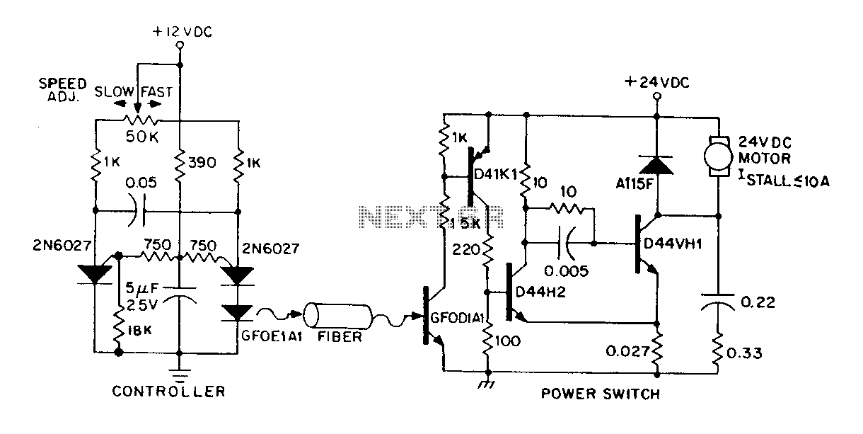
A DC power supply can be controlled through an optical fiber. The circuit includes a small DC motor (1/12 hp) that offers an isolated speed control channel. The control logic operates as an independent module, consuming 300 mW of...
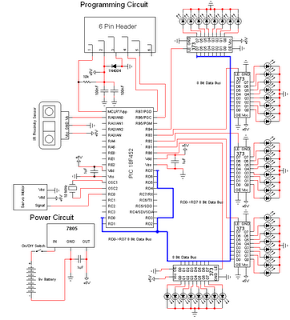
A buzzer circuit utilizes a PIC microcontroller to drive a piezo buzzer. The microcontroller is a low-power processor that is ideal for portable and compact devices where battery conservation is essential. The buzzer circuit employs a PIC microcontroller, which serves...
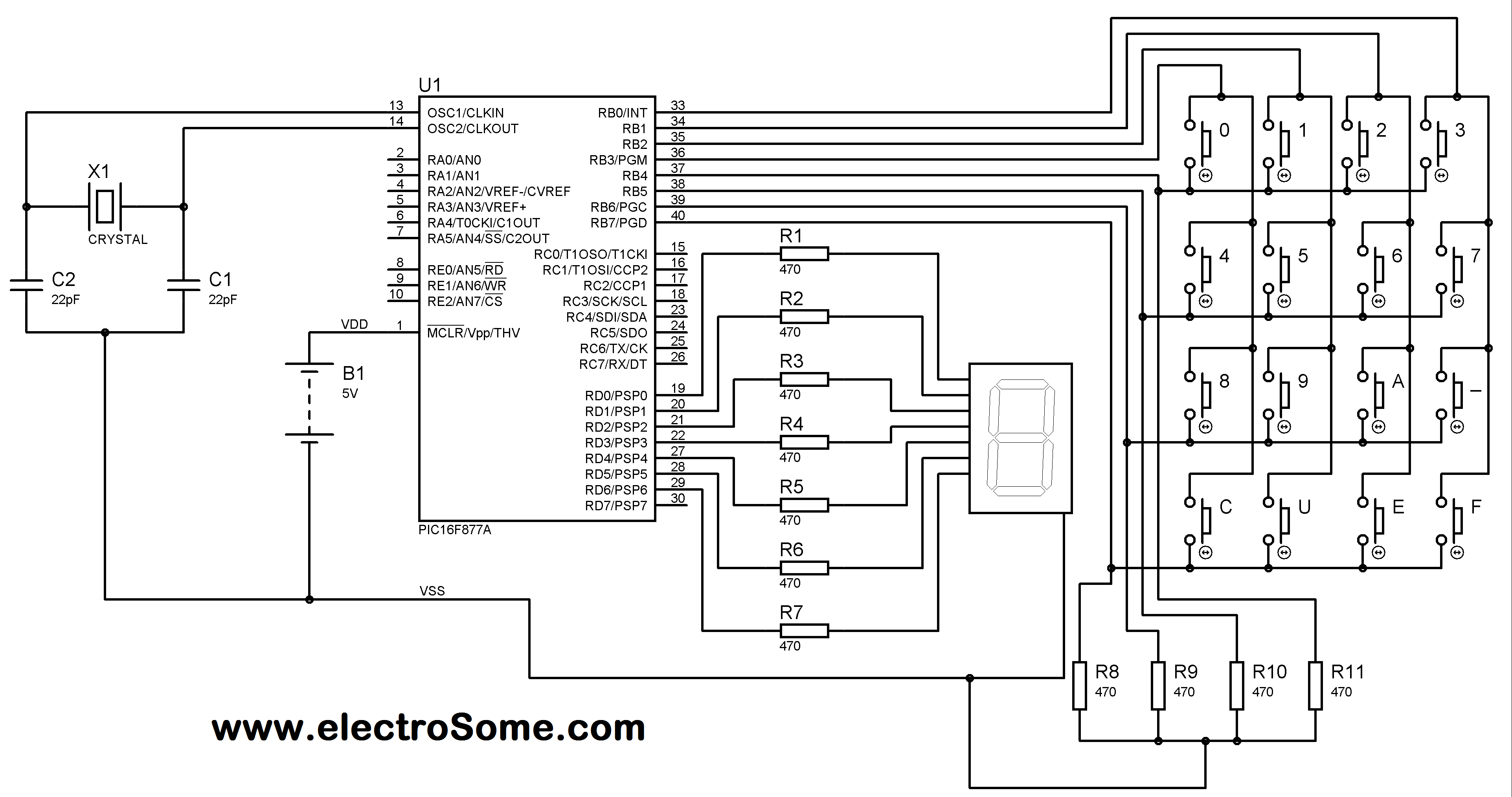
A matrix keypad is a highly useful and user-friendly component in the design of applications such as calculators and telephones. It consists of push-button switches arranged in rows and columns. For instance, interfacing a 4x4 (16 keys) matrix keypad...
The personal radar system utilizes the PIC microcontroller PIC18F452 as a hobby project. The attached circuit diagram of the radar may appear simple; however, careful analysis of the PIC18F452 radar circuit is necessary to prevent damage. This personal radar...
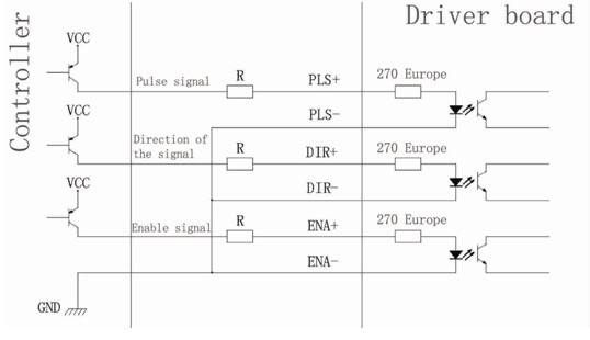
Connection of a drive and a two-phase hybrid stepper motor using a four-wire system, with the motor windings configured in both parallel and series connections. This method allows for high-speed performance, although it requires a large drive current (1.73...
The following circuit illustrates a Bass and Treble Controller Circuit. This circuit is constructed based on the classic Baxandall tone control circuitry. The Bass and Treble Controller Circuit is designed to adjust the low and high-frequency response of audio signals,...