
Step-down autotransformer rotor excitation frequency starting circuit

The circuit operates through a series of controlled steps that ensure smooth acceleration of the motor while maintaining system stability. Initially, the auto step-down transformer (ZQB) reduces the voltage supplied to the motor, allowing it to start under low load conditions. This gradual increase in voltage prevents sudden surges that could damage the motor or associated components.
As the motor reaches a certain speed, defined as the quasi-synchronous speed, the circuit activates a resection mechanism. This mechanism involves the shorting of discharge resistors (R), which are connected to the rotor winding. The purpose of these resistors is to dissipate energy and stabilize the rotor's magnetic field during the transition to synchronous operation. By connecting the DC excitation to the rotor winding at this point, the system ensures that the rotor aligns with the rotating magnetic field produced by the stator, achieving synchronous operation.
The transition from starting to synchronous operation is critical for the efficiency and longevity of the motor. The design of the circuit allows for precise control over the timing of these operations, ensuring that the motor operates within safe parameters while maximizing performance. The inclusion of feedback mechanisms may also be considered to monitor the motor's speed and adjust the excitation levels dynamically, further enhancing operational reliability.
Overall, this circuit design exemplifies a robust approach to motor control, balancing the need for an effective startup sequence with the requirements for operational efficiency in synchronous applications. Circuit shown in Figure 3-187. When you start, then people start auto ZQB step-down transformer. After a period of delay, ZQB out of operation, the motor increases the speed at full pressure. When the speed rises above and quasi-synchronous speed, resection (short) discharge resistors R :, join DC excitation in the rotor winding, synchronous motor synchronous operation was led people to end the startup process.
Related Circuits

The TEA5551T monolithic integrated radio circuit can be utilized to design an AM radio receiver circuit intended for portable use with headphones. This circuit incorporates all necessary components for a complete AM radio receiver, including a fully integrated AM...
The metal detector circuit consists of a probe oscillator, a PLL (phase-locked loop) circuit, and an audio alarm circuit. The probe oscillator includes a detection coil (L), transistor (V1), and several resistors (R1 to R3) and capacitors (C1 to...
This circuit is 12 volt motors and lights well regulated. The scheme operates with PWM (Pulse Width Modulation). By IC1, a 555 is a square wave generated by a controllable duty cycle. This means that the width of the...
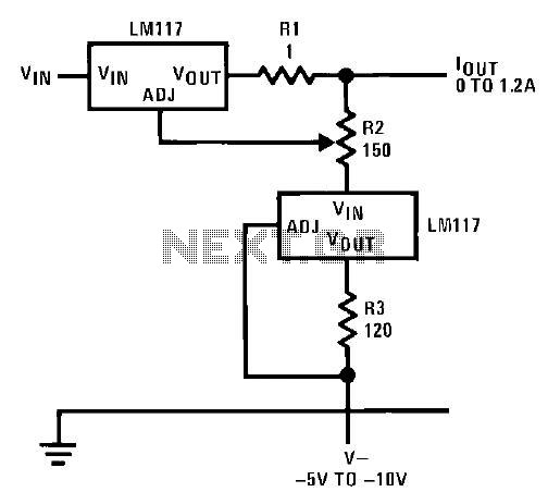
This circuit illustrates an adjustable regulator configuration that incorporates a voltage regulator. In this design, the LM117 regulator is utilized instead of the LM113 diode for reference. Both regulators necessitate a negative supply to function correctly with respect to...
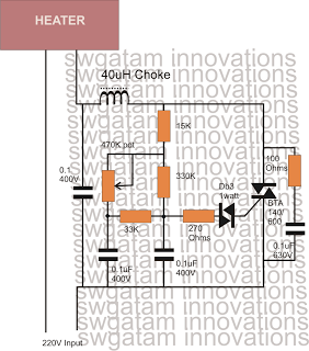
Controlling heaters rated up to 1500 watts requires stringent specifications for the controlling unit to ensure safe and effective operation. The introduction of advanced snubber-less Triacs and Diacs has made it relatively easier to implement heater controllers at high...
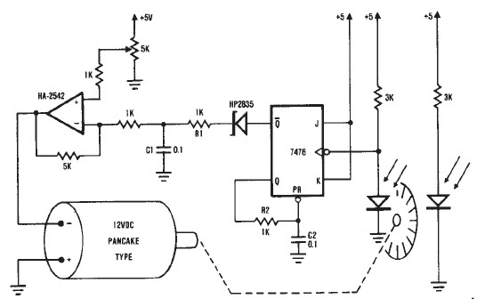
A simple encoder circuit for a DC motor can be constructed using this circuit diagram. The system consists of the HA-2542, a small 12-V DC motor, and a position encoder. During operation, the encoder generates a series of constant-width...