
Quadrature Oscillator with TLV2474
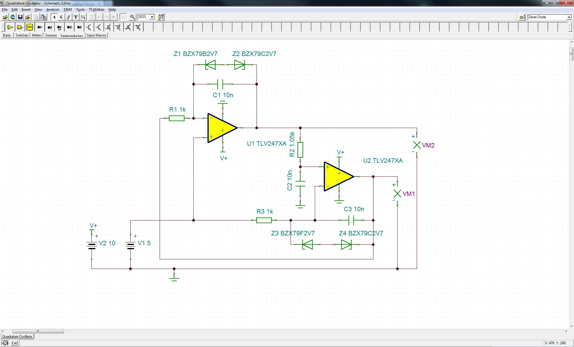
The circuit in question appears to be a Wien Bridge Oscillator, a type of electronic oscillator that generates sine waves. The Wien Bridge Oscillator typically consists of an operational amplifier (op-amp) and a bridge circuit made up of resistors and capacitors that determine the frequency of oscillation. By adjusting the resistance of R2, the gain of the circuit can be modified to achieve the necessary conditions for oscillation.
In the context of this design, the use of Zener diodes in the feedback loop serves to limit the output voltage, preventing clipping and allowing for a cleaner sine wave output. This is crucial in oscillators, as distortion can lead to unreliable performance. The choice of Zener diodes must be compatible with the power supply voltage; in this case, a 5V supply may require diodes with lower breakdown voltages to function correctly.
The introduction of a nonlinear element, such as a lamp or Zener diodes, can stabilize the oscillation by providing automatic gain control. This optimization can help manage the trade-off between gain and distortion, which is a common challenge in oscillator design. A potentiometer can also be incorporated into the circuit to allow for fine-tuning of the oscillation frequency and amplitude.
For practical implementation, careful consideration should be given to the component values and the power supply used. Testing the circuit with real elements will provide valuable insights into its performance and any adjustments that may be necessary. Additionally, documenting any observations during experimentation can be beneficial for future reference or for others attempting similar designs.I did some quick playing with the circuit. It is very close to sustaining oscillation. Changing R2 to 10. 5k will cause it to sustain oscillation. The original authors of the note that you reference are no longer with TI so we cannot consult with them. Oscillators of this type can be tricky and there is a tradeoff between providing enough gain to o scillate and overloading into strong distortion. This circuit would probably require optimization with a nonlinear element to better control the feedback for reliable performance. You mean like the lamp in Hewlett`s Wien Bridge Oscillator I was actually hoping to get around something like this.
Maybe a pot and a little fiddling with the tuning could make it work as well I`ll try to set this up with real elements some time soon and see if it works. Sorry to reopen this thread, but I have been thinking about what you said about non-linear feedback and have placed two Zener diodes in the feedback loops of both amps.
Without the diodes the output voltages run against the rails and clip but with them the output becomes a pure sine/cosine wave. However this does not work for 5 V supply which I assume is due to the breakdown voltages of the diodes.
I am posting this partly to share it with anyone who might want to do something similar in the future and partly to ask if anyone sees any pitfalls or redundancies I overlooked. All content and materials on this site are provided "as is". TI and its respective suppliers and providers of content make no representations about the suitability of these materials for any purpose and disclaim all warranties and conditions with regard to these materials, including but not limited to all implied warranties and conditions of merchantability, fitness for a particular purpose, title and non-infringement of any third party intellectual property right.
TI and its respective suppliers and providers of content make no representations about the suitability of these materials for any purpose and disclaim all warranties and conditions with respect to these materials. No license, either express or implied, by estoppel or otherwise, is granted by TI. Use of the information on this site may require a license from a third party, or a license from TI. Content on this site may contain or be subject to specific guidelines or limitations on use. All postings and use of the content on this site are subject to the Terms of Use of the site; third parties using this content agree to abide by any limitations or guidelines and to comply with the Terms of Use of this site.
TI, its suppliers and providers of content reserve the right to make corrections, deletions, modifications, enhancements, improvements and other changes to the content and materials, its products, programs and services at any time or to move or discontinue any content, products, programs, or services without notice. 🔗 External reference
Related Circuits
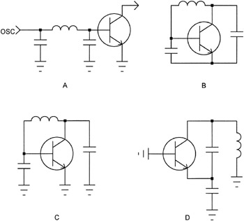
The open-loop concept of oscillator design is often met with considerable skepticism by engineers familiar with classic oscillator terminology. For clarity, consider Figure 2-4A, where the oscillator cascade is illustrated with only the RF components. The circuit is then...
The circuit uses two CMOS ICs. IC1 uses inverters connected as a Colpitts oscillator of 100KHz; the LC frequency determining elements being the search coil and parallel resonating capacitor. An 80 turn close wound 30swg 100mm diameter coil will...
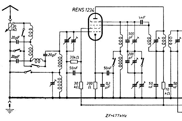
The schematic of the mixer section illustrates an oscillator. The oscillator's LC circuit has only two connections to the valve and does not include a tap or tickler coil. Oscillations will only occur if the tube provides a negative...
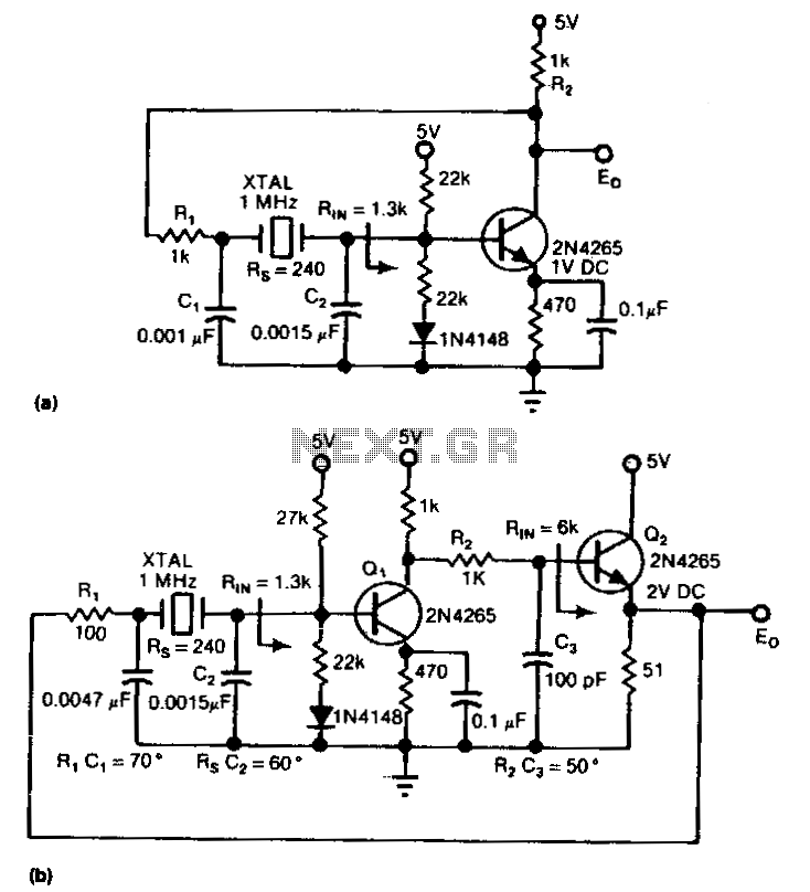
The circuit is an inverter configured as a linear amplifier. By incorporating a crystal and capacitors into the feedback path, the amplifier is transformed into an oscillator, enabling it to oscillate at or near the crystal's resonant frequency. Trimmer...
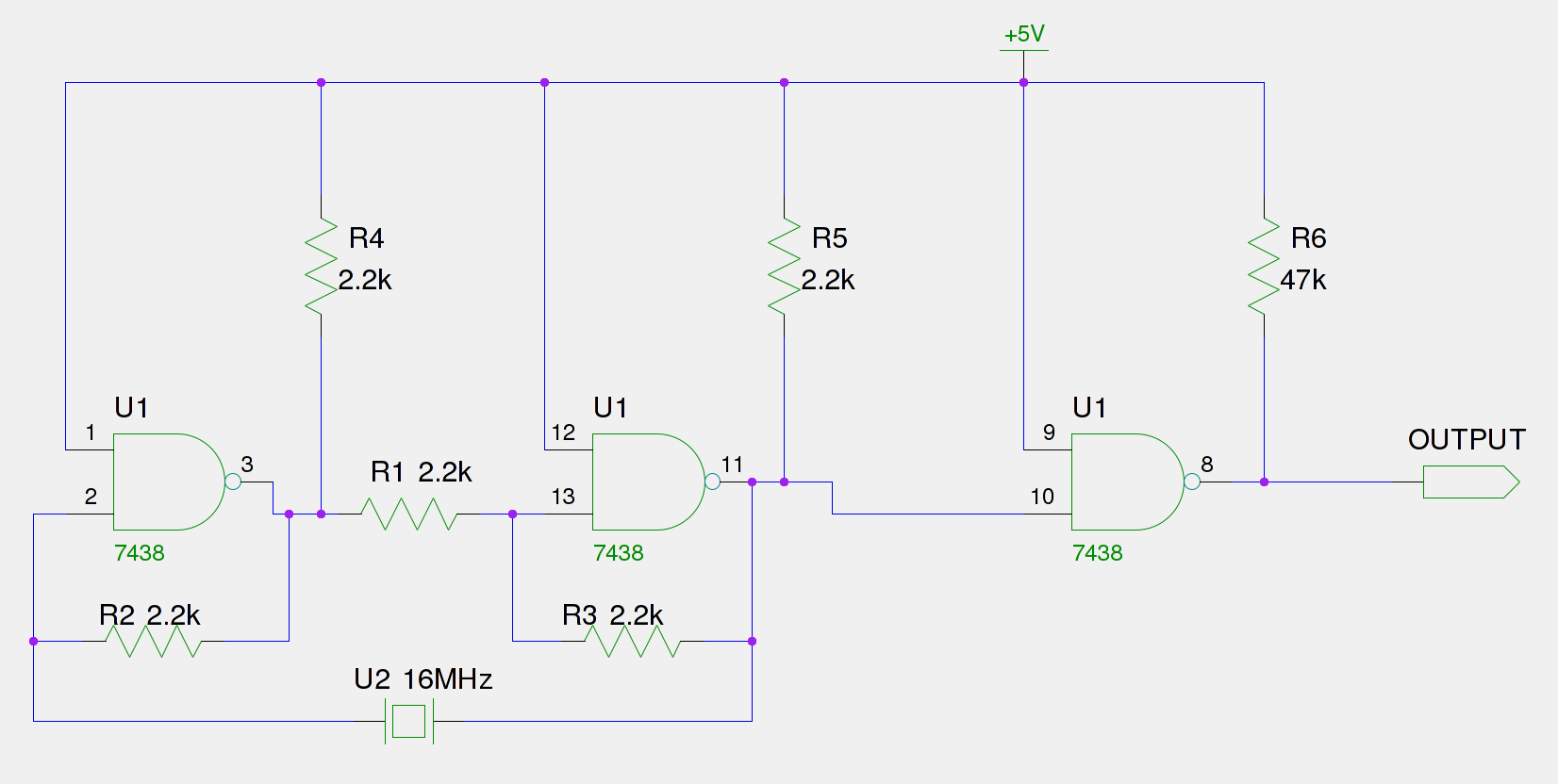
An old Eistar SJ-1 digital pulser has been acquired. However, the frequency it generates is consistently 66% of the expected output. The frequency observed at the frequency stage (Pin 11) is 66% of the 16 MHz crystal, which equates...
This is a grid dip oscillator (GDO) circuit developed by Luigi Falcone. The circuit uses seven plug-in coils that cover the frequency range of 3.0 to 30 MHz. It can be connected to a frequency meter through the coaxial...
Warning: include(partials/cookie-banner.php): Failed to open stream: Permission denied in /var/www/html/nextgr/view-circuit.php on line 713
Warning: include(): Failed opening 'partials/cookie-banner.php' for inclusion (include_path='.:/usr/share/php') in /var/www/html/nextgr/view-circuit.php on line 713