
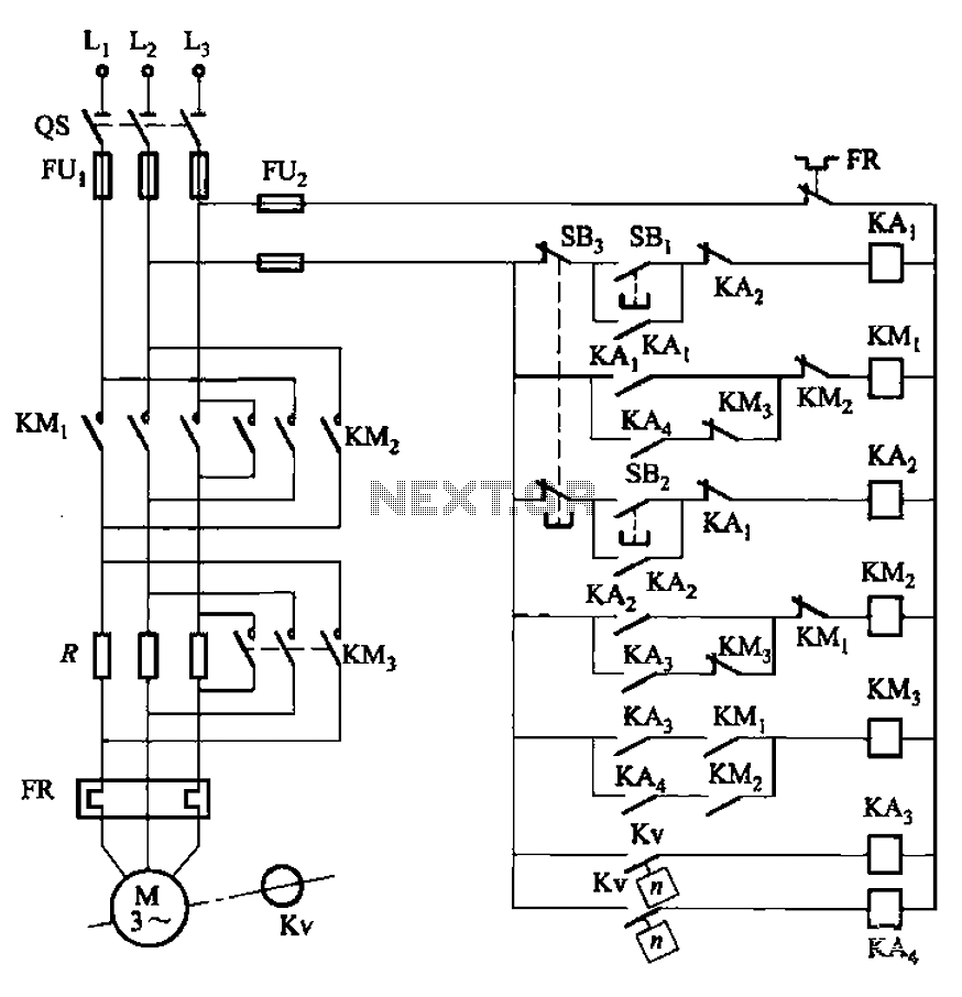
Quadruple semi-continuous casting machine speed control circuit

The described circuit operates within the framework of a simple yet effective control system for a DC motor. The main circuit integrates various components to ensure optimal performance and protection of the motor. The trigger circuit is responsible for initiating the operation of the motor by providing the necessary starting signal.
The speed negative feedback mechanism plays a crucial role in maintaining the desired operational speed of the motor. It continuously monitors the motor speed and adjusts the excitation voltage accordingly to compensate for any deviations from the set speed. This feedback loop enhances the stability of the system.
The negative feedback differential voltage circuit further refines the control by comparing the actual speed of the motor with the desired speed, allowing for precise adjustments. The current cut-off circuit is a safety feature that disconnects the motor in the event of an overload, preventing potential damage.
Additionally, the loss of field protection circuit is implemented to safeguard against situations where the field winding loses its excitation, which can lead to unstable motor operation. The use of a single-phase circuit is appropriate for the low power rating of the motor, simplifying the design and reducing costs.
The variable transformer Tz, in conjunction with the rectifier bridge, converts the AC input voltage into a suitable DC voltage, VC3, which serves as the excitation voltage for the motor and tachometer generator. The master adjust potentiometer RP3 provides an interface for operators to manually adjust the motor speed, enabling flexibility in various applications where speed control is necessary.
Overall, this circuit design incorporates multiple safety and control features to ensure reliable operation of the DC motor while allowing for user-adjustable speed settings. Circuit from the main circuit, trigger circuit, speed negative feedback, negative feedback differential voltage, current cut-off circuit, loss of field protection and other com ponents. Since the motor power is small (1. lkW), so the use of single-phase circuits. Figure, BQM and BQTG are DC motor M and the tachometer generator TG field winding. They consist of variable Tz by the rectifier bridge voltage VC3 offers the exciting voltage. Master adjust potentiometer RP3, can change the motor speed.
Related Circuits
Motor control, energy efficiency of inverter (AC drive) selection, and parameters setting guidance in the mining industry: vector control, open loop or closed loop control, with energy braking unit or energy feedback unit. In the context of motor control for...
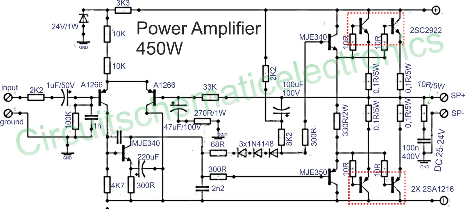
Below is a circuit of power amplifiers with a power output of 450 watts in mono mode. These amplifiers are frequently utilized in high-power applications, suitable for events, and designed for enclosed spaces. This amplifier is appropriate for woofers...
This triac-based 220V AC motor speed controller circuit is designed for controlling the speed of small household motors, such as drill machines. The motor speed can be adjusted by altering the setting of P1, which determines the phase of...
Equipment designed to detect changes associated with fire, monitor the integrity of their operations, and provide automatic control and transmission of information necessary to prepare the facility for fire, temperature, and light based on a predetermined sequence. The panel...
The circuit illustrated in Figure 3-130 differs from the circuit in Figure 3-129 in that when the stop button SB3 is pressed, the electric motor initiates braking. Furthermore, during both the startup and braking phases, the motor power lines...
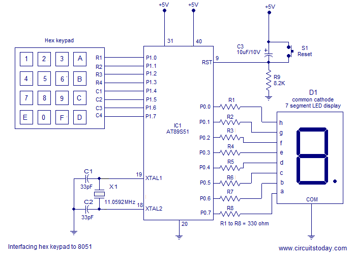
Interfacing a hex keypad to an 8051 microcontroller. The AT89S51 is utilized in this setup. A circuit diagram and assembly language program are included. A testing video is also provided. The interfacing of a hex keypad with the AT89S51 microcontroller...