
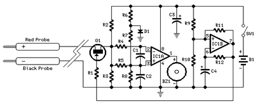
Quick On-Board Junction TesterCircuit

The acoustic check of transistor and diode junctions is a method used to assess the functionality of these semiconductor devices. This technique relies on the audible feedback generated when a signal is applied to the junctions. The tester emits a tone that varies in pitch or volume based on the characteristics of the junction being tested. For instance, a healthy diode will produce a distinct sound when forward-biased, while a malfunctioning diode may not generate any sound, indicating an open circuit.
In addition to testing individual components, this device functions as a continuity tester, allowing users to verify the integrity of electrical connections within a circuit. By connecting the tester's probes across the points of interest, the user can detect short circuits or broken tracks on printed circuit boards (PCBs). A continuous tone signifies a good connection, while silence indicates an open circuit or break in the track.
This testing technique is particularly valuable in troubleshooting electronic devices, as it provides immediate auditory feedback, allowing for efficient identification of faults without the need for visual inspection or complex measurement equipment. The simplicity and effectiveness of this method make it an essential tool for electronics engineers and technicians in both design and repair environments.Acoustic check of transistor and diode junctions, Also suitable as continuity tester Short circuits or broken pcb tracks can be easily recognized by means.. 🔗 External reference
Related Circuits
Short circuits or broken PCB tracks can be easily identified using a multimeter; however, this tool may yield inaccurate results when testing the efficiency of a transistor or diode unless the component is unsoldered and removed from the PCB....
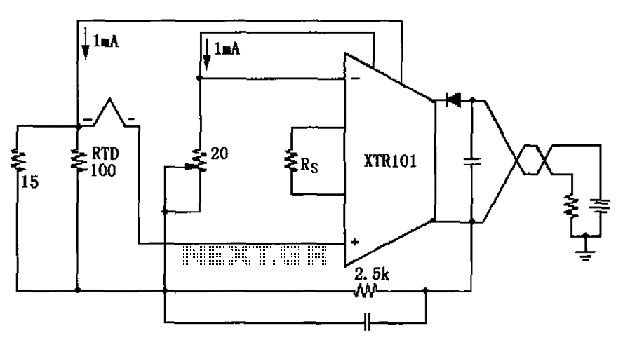
The circuit utilizes a type J RTD (Resistance Temperature Detector), where the resistance value is directly related to the temperature. Calibration of the zero point is facilitated by a 20-ohm adjustment potentiometer as specified by the manufacturer. The schematic features...
Connect all connectors onto the flat cable using a small vice. This creates an instant male-male, male-female, and female-female serial adapter, along with a short extender cord. This tool is essential for those experimenting with serial ports. An additional...
Due to the increased level of the transistor amplifier circuit, the control circuit's performance in Figure 16-6 is more sensitive and can accept input control signals superimposed on others (such as voltage, current, and speed feedback signals) to meet...
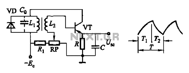
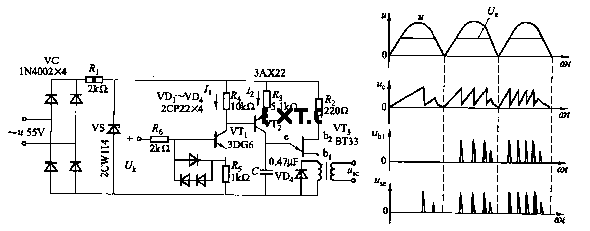
Common non-sinusoidal oscillator circuit, waveform and frequency formula - pulse wave oscillator - single-junction transistor blocking oscillator. The common non-sinusoidal oscillator circuit described is a pulse wave oscillator that utilizes a single-junction transistor in a blocking configuration. This type of...
This document presents a very low-power monolithic 1.9GHz silicon Low Noise Amplifier (LNA) that operates with a total current consumption of 1.75mA, which includes the bias circuit. The described Low Noise Amplifier (LNA) operates at a frequency of 1.9GHz, making...