
Radio Buttons Using Push On Switch Latching Circuit

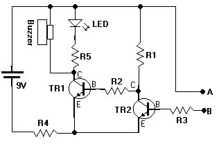
The switching circuit operates on the principle of latching, allowing multiple push buttons to function as a set of radio buttons. When one button is pressed, it activates the interlocking circuit, ensuring that only one button remains active at any given time. This is achieved through a combination of resistors, transistors, and possibly diodes, which work together to maintain the state of the last button pressed while deactivating the others.
The circuit typically includes a power source, which energizes the components, and a ground connection to complete the circuit. Each push button is connected to a transistor that serves as a switch. When a button is pressed, it sends a signal to the base of the corresponding transistor, allowing current to flow from the collector to the emitter, thus turning it on. The interlocking mechanism is established by connecting the output of each transistor to the base of the others, creating a feedback loop that ensures only one can be active.
Additional components may include pull-down resistors to prevent floating states when buttons are not pressed, and capacitors for debouncing to eliminate noise from mechanical switch contacts. This design is particularly useful in applications where a user must select one option from a set, such as in user interfaces for electronic devices, ensuring a clear and intuitive operation.This is a switching circuit that provide latching mechanism to make a set of radio buttons using push buttons. This circuit consist of interlocking circuit.. 🔗 External reference
Related Circuits
This document presents a water sensor circuit designed to monitor soil moisture levels for plants. This circuit is straightforward and is constructed using five resistors, two transistors, an LED, a buzzer, and a battery. The operation of the circuit...
This project Digital gated Emulator using Microcontroller is used to emulate the basic gates such us NOT, OR, AND. The system has the selector switch by which we can select any gate. The system has two inputs and one...
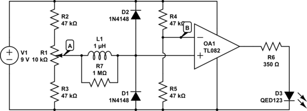
The circuit above is a canonical AC coupled common emitter amplifier, which is typically used as a linear amplifier rather than a switch that activates when the input exceeds a certain level. The AC coupled common emitter amplifier is...
The circuit on this page is for a simple light detector circuit board that has 8 detectors that can be used with visible or infrared light systems. The detectors use LM339 voltage comparators as the active element. Phototransistors or...
Visit eBid United Kingdom, the online marketplace without fees - buy and sell today. eBid United Kingdom serves as an online marketplace that facilitates buying and selling transactions without imposing fees on its users. This platform offers a user-friendly interface...
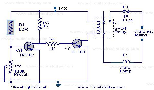
The circuit diagram of an Automatic Street Light Controller Circuit is explained in this post. The Automatic Street Light Controller Circuit is designed to automatically turn on street lights at dusk and turn them off at dawn. This functionality is...