
Radio receiver circuit for long and medium wave

The described oscillating circuit utilizes a ferrite bar as its core, which enhances the inductive properties of the windings. The choice of ferrite material is critical, as it provides the necessary magnetic permeability to optimize the circuit's performance across the desired frequency ranges. The windings "1-2" and "3-4" are configured to create two distinct inductors, allowing the circuit to be tuned for long-wave or medium-wave reception.
For long-wave applications, the winding specifications of 135 turns for "1-2" and 20 turns for "3-4" ensure that the circuit can resonate at lower frequencies, which are typically below 300 kHz. Conversely, the medium-wave configuration, with 75 turns for "1-2" and 7 turns for "3-4", allows for resonance at frequencies typically ranging from 530 kHz to 1700 kHz. The use of CuEm wire with a diameter of 0.15 mm is appropriate for minimizing resistive losses while maintaining adequate flexibility for winding.
The integration of a variable capacitor (40-400 pF) in parallel with winding "1-2" is essential for tuning the circuit. This capacitor allows for fine adjustments to the resonant frequency, enabling the user to select specific stations by varying the capacitance. The presence of high-impedance headphones (1000-2000 ohms) ensures that the circuit can effectively drive the audio signal without loading down the oscillating circuit, which could lead to distortion or loss of signal quality. The additional 10 nF capacitor in parallel with the headphones serves to filter high-frequency noise, providing a clearer audio output.
Overall, this oscillating circuit design is well-suited for amateur radio enthusiasts and provides a practical means of receiving long and medium wave signals with clarity and precision. Proper construction techniques and component selection are crucial for achieving optimal performance and reliability in operation.Oscillating circuit (coil) are made on a ferrite bar. If you wish to listen long waves winding "1-2" has 135 turns and 3-4 has 20 turns. If you wish to receive medium wave winding "1-2" has 75 turns, and "3-4" has 7 turns (wire used must be CuEm 0. 15mm). In parallel with the winding 1-2 is necessary to connect a 40-400pF variable capacitor. Listen ing signal is made using high impedance headphones to 1000-2000 ohms, which have a capacitor of 10nF in parallel. 🔗 External reference
Related Circuits
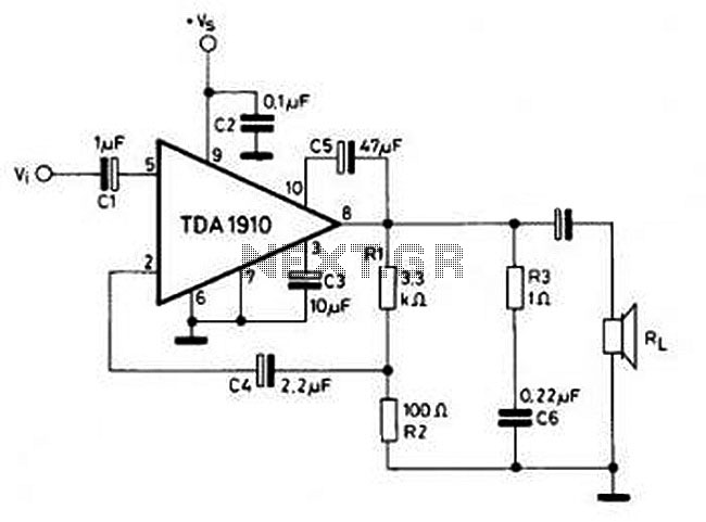
This circuit is simple and inexpensive, which is its primary advantage. Although the output power is not high, the audio quality is good due to the TDA1910's very low noise feature. This circuit is suitable for use as a...
This application note explains how the transfer function of most operational amplifier circuits can be derived through a straightforward process of nodal analysis. The transfer function of operational amplifier (op amp) circuits is a critical aspect for understanding their behavior...
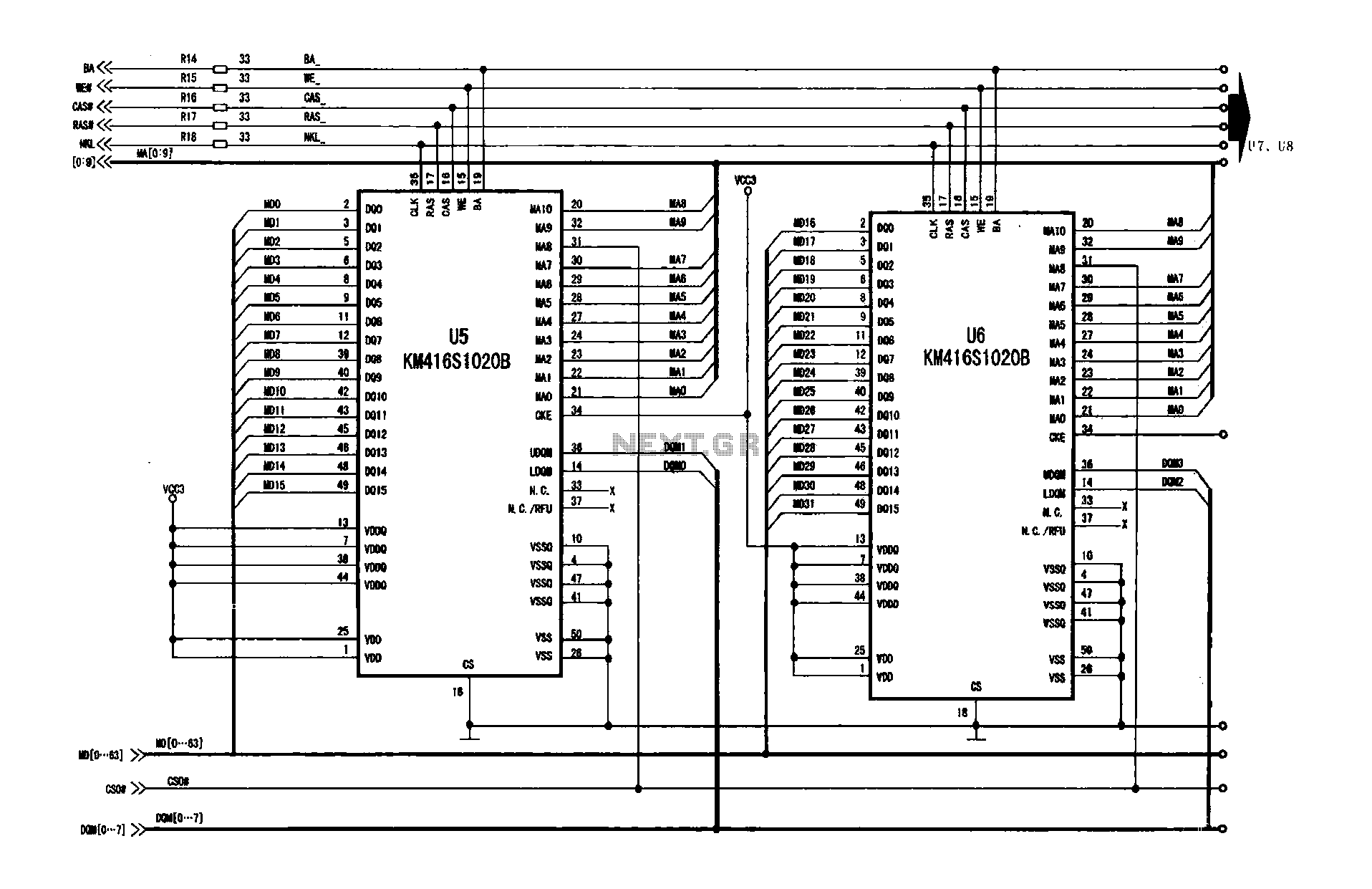
A digital signal processing circuit that operates in conjunction with a memory system for temporarily storing image data. The DPTVT-3D/MV digital processing chip requires four KM416S102 memory units, each providing 16 MB of digital memory. The circuit structure is...
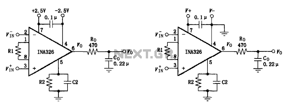
The basic connection circuit for the INA326/327 includes signals and power. A 0.1 µF capacitor is selected for power supply filtering and should be placed as close to the chip's supply pin as possible. Ro and Co serve as...
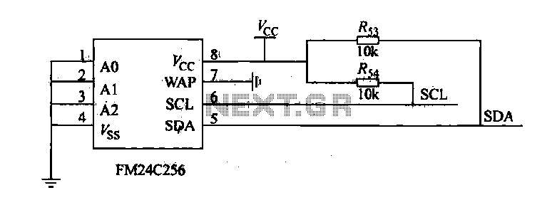
The FM24C256 is utilized as a slave interface circuit in an I2C bus configuration, with the address format specified in Table 27-3. The address pins A2, A1, and A0 are set to low; however, for extended storage capacity, adjustments...
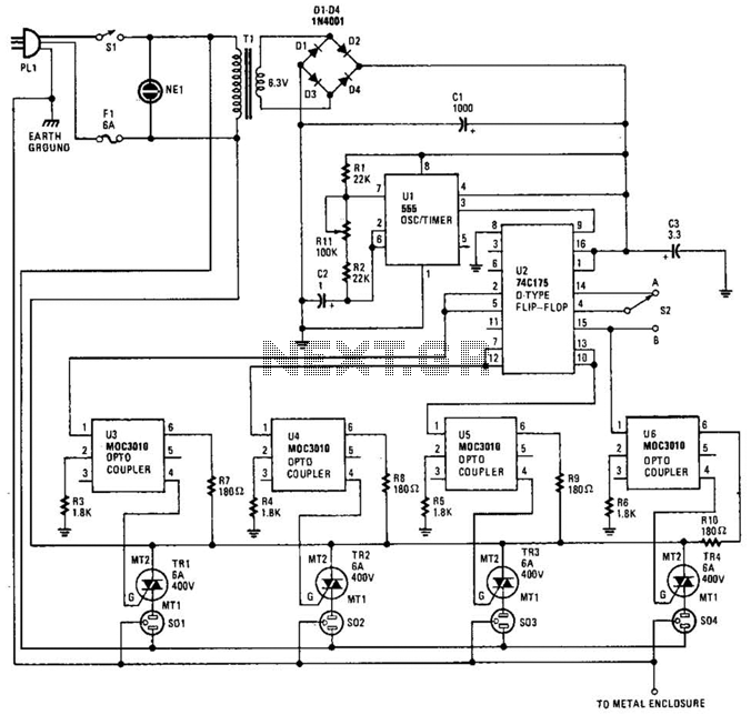
The integrated circuit U1 (a 555 oscillator/timer) is configured as a conventional pulse generator. The frequency of the pulse generator is adjusted using potentiometer R11. Resistor R2 limits the maximum frequency attainable. The output from the pulse generator is...